


14
to the maximum equivalent flue length) between the boiler and
vertical flue assembly.
Ensure that any horizontal sections of the flue system have a
minimum 1º; maximum 3º fall back to the boiler (1º = 17mm per
1000mm).
NOTE
When cutting an extension to the required length, you must
ensure that the excess is cut from the plain end of the extension.
Remove any burrs, and check that any seals are located
properly.
You must ensure that the entire flue system is properly supported
and connected.
4.5.3 TWIN FLUE SYSTEM
The Vokèra twin flue system enables greater flue distances to
be achieved than that of a concentric flue system. It can be used
for horizontal or vertical applications, however the twin flue
system must be converted to the dedicated concentric flue kit
for termination. It is essential that the installation of the twin flue
system be carried out in strict accordance with these instructions.
Fig. 14
HORIZONTAL TERMINATION
The twin flue system must be converted to the dedicated
concentric flue kit for termination.
•
The horizontal terminal is supplied with a built-in converter
box and cannot be shortened.
•
A 130mm hole is required for the passage of the concentric
terminal through the wall.
•
The air inlet pipe must always be level with or below, that of
the exhaust pipe.
Depending on site conditions it may be preferable to install the
terminal assembly prior to fitting the twin flue pipes.
Mark and drill a level 130mm hole for the passage of the
horizontal flue terminal. Insert the terminal assembly into the
flue hole.
Push-fit the twin flue pipes onto the concentric to twin converter
box ensuring that the exhaust pipe connects to the exhaust
connection on the concentric to twin converter.
If necessary cut the plain ends (male) of the twin flue pipes to
allow connection to the concentric to twin converter.
NOTE
Before cutting twin flue pipes ensure allowances have been
made for connection onto the previous piece and onto the
concentric to twin converter. The last twin flue pipes must be
pushed 50mm onto the male spigots of the concentric to twin
converter.
NOTE
Seal the flue terminal assembly to the wall using cement or a
suitable alternative that will provide satisfactory
weatherproofing. The interior and exterior trim can now be
fitted.
VERTICAL TERMINATION
The twin flue system must be converted to the dedicated
concentric flue kit for termination.
•
The vertical terminal is supplied with a built-in converter box
and cannot be shortened.
•
A 130mm hole is required for the passage of the concentric
terminal through the ceiling and/or roof.
Depending on site conditions it may be preferable to install the
terminal assembly prior to fitting the twin flue pipes.
Fit the appropriate flashing plate to the roof and insert the
vertical flue terminal through the flashing plate from the outside,
ensuring that the collar on the flue terminal fits over the flashing.
Push-fit the twin flue pipes onto the concentric to twin converter
ensuring that the exhaust pipe connects to the exhaust
connection on the concentric to twin converter.
If necessary cut the plain ends (male) of the twin flue pipes to
allow connection to the concentric to twin converter.
B
A
C
Fig. 15
Total flue length 80
Restrictor required
Up to 2+2 metre
42 mm diameter
From 2+2 to 6+6 metre
44 mm diameter
From 6+6 to 16+16 metre
Not installed
GUIDANCE NOTES ON TWIN FLUE INSTALLATION
•
The flue must have a fall back of 1º back to the appliance to
allow any condensate that forms in the flue system to drain
via the condensate drain.
Consideration must also be given to the fact that there is the
possibility of a small amount of condensate dripping from the
terminal.
•
Ensure that the entire flue system is adequately supported,
use at least one bracket for each extension.
•
Extreme care must be taken to ensure that no debris is
allowed to enter the flue system at any time.
•
As the exhaust outlet pipe can reach very high temperatures
it must be protected to prevent persons touching the hot
surface.
Reduction for bends
Bend
Reduction in maximum flue length for
each bend
45º bend
0.5 metre
90º bend
0.8 metre
Twin flue accessories
Part No.
Description
Length
20006933
Twin adapter kit
N/A
MOUNTING THE BOILER
The fixing holes for the wall-mounting bracket should now be
drilled and plugged, an appropriate type and quantity of fixing
should be used to ensure that the bracket is mounted securely.
Once the bracket has been secured to the wall, mount the
appliance onto the bracket.
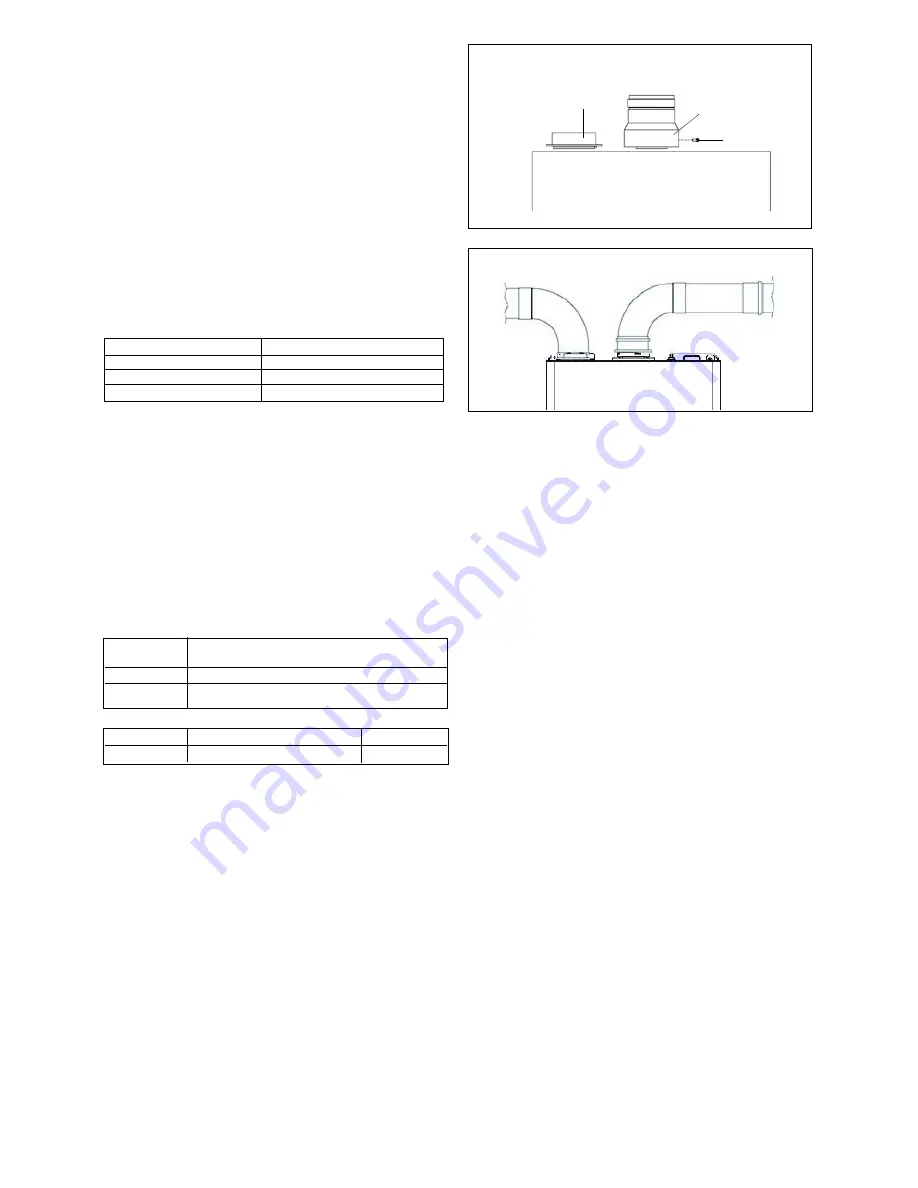
INSTALLATION OF TWIN ADAPTOR KIT (fig. 12 & 13)
•
Insert the exhaust connection manifold (A) onto the
appliance flue outlet.
•
Remove the blanking plate (located to the left of the appliance
flue outlet) and – using the same screws – install the air inlet
plate (B).
•
Using the hole in the exhaust connection manifold as a
guide, drill a 3mm hole in the appliance flue spigot and
secure the exhaust manifold connection to the flue spigot
using the screw provided (C).
•
Using the two holes in the air inlet plate as a guide, drill a 3mm
hole in each and secure the air inlet pipe/bend using the
screws provided.
The twin flue pipes extensions and accessories can now be
installed by pushing together (the plain end of each extension
or bend should be pushed approximately 50mm into the
female socket of the previous piece).


