Vitec Multimedia CellCom 10 Скачать руководство пользователя страница 55

C E L L C O M   1 0   W I R E L E S S   C O M M U N I C A T I O N   S Y S T E M  

6 - 5

Belt Clip 

The belt clip is spring-loaded, with enough tension to hold the beltpack to the 
user’s belt and against the hip. Note that the upper portion of the rear of the 
beltpack, connected to the belt clip, is a separate piece; the entire belt clip 
assembly may be replaced in case of damage. 

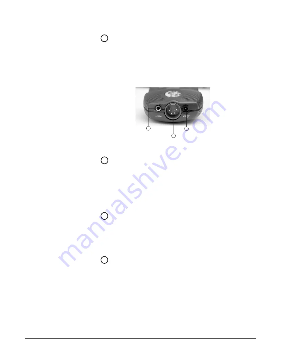
BELTPACK BOTTOM CONNECTOR SECTION

Figure 5: View of Bottom of Beltpack

Data Connector 

This 3.5 mm (1/8 inch) tip-ring-sleeve (TRS) connector is used to connect the 
beltpack to a computer in order to identify the beltpack to the base station 
during initial registration and system setup. It may also be used if an upgrade to 
the beltpack firmware is ever required in the future, to add new features and 
capabilities. See the section “Registering the Beltpack with the Base Station” for 
further details. 

Headset Connector

The male 4-pin headset connector provides audio pathways for the headset 
microphone and headset earpiece(s). This connector supports all Clear-Com and 
compatible headsets using female 4-pin connectors. It will support dynamic 
microphones. 

Battery Recharger Connector 

The CellCom 10 beltpack features an internal battery charger when you insert 
four AA-format NiMH batteries to power the unit. The recharger circuit 
includes a thermistor that senses the temperature of the battery pack to prevent 
overcharging. To use this internal recharger, plug in the small barrel connector on 
the supplied universal power supply into the beltpack connector, and then plug 
the supply into the local AC current. The beltpack will automatically shut off 
when the charging PSU is plugged into it. While it is charging, the beltpack 
cannot be turned on. You can only turn it on when the chargind PSU is 
disconnected. A full charge takes approximately 3 to 4 hours depending on the 
battery capacity. 

3

Ba

tt

ery Recharger Connec

t

or

Da

t

a Connec

t

or

1

Headse

t

 Connec

t

or

2

3

1

2

3

Содержание CellCom 10

Страница 1: ...DIGITAL WIRELESS MATRIX I N S T R U C T I O N M A N U A L CellCom 10...

Страница 2: ...ons Inc 4065 Hollis Street Emeryville CA 94608 3505 U S A Clear Com is a registered trademark of Vitec Group Communications The Clear Com Logo is a registered trademark of Vitec Group Communications C...

Страница 3: ...om Systems 4 4 Connecting to 4 Wire and Digital Matrix Intercom 4 6 Connecting to a Program Audio Source 4 9 Connecting to the Stage Announce Output 4 9 Connecting to a PC 4 10 Linking Two Base Statio...

Страница 4: ...s 6 10 OPERATING THE CELLCOM 10 TRANSCEIVER ANTENNA 7 1 Transceiver Antenna 7 1 Transceiver Antenna Splitter 7 4 INSTALLING A SYSTEM 8 1 Initial System Setup 8 1 Doing a Site Survey to Determine Cover...

Страница 5: ...safety If the provided plug does not fit into your outlet consult an electrician for replacement of the obsolete outlet 7 Protect power leads from being walked on or pinched particularly at plugs at c...

Страница 6: ...evant CE FCC UL and CSA specifications set out below EN55103 1 Electromagnetic compatibility Product family standard for audio video audio visual and entertainment lighting control apparatus for profe...

Страница 7: ...vii This device complies with Part 15 of the FCC Rules Operation is subject to the following two conditions 1 this device may not cause harmful interference and 2 this device must accept any interfer...

Страница 8: ...C E L L C O M 1 0 W I R E L E S S C O M M U N I C A T I O N S Y S T E M viii...

Страница 9: ...hes for unused radio frequency RF channels CellCom avoids the noise and interference issues associated with traditional wireless systems using congested UHF and VHF bands Figure 1 A CellCom 10 Antenna...

Страница 10: ...meters 3 200 feet over CAT 5 cable from the base station avoiding expensive RF cable Five character labels for each beltpack and wired connection Communication groups can be created customized and as...

Страница 11: ...CAT 5 cable Each antenna provides an area or cell in which four to five full duplex beltpacks can operate Figure 2 above shows an example configuration Beltpacks can roam among and between cells with...

Страница 12: ...a large scale permanent broadcast facility Note Each antenna is designed to handle five beltpacks simultaneously in good conditions However if interference or propagation problems occur in an area to...

Страница 13: ...en members of the group Note For a quick overview of the CellCom 10 programming menus refer to Appendix 2 CONNECTING THE BASE STATION To connect the CellCom base station to a party line beltpack 1 Mak...

Страница 14: ...then NONE See Figure 2 Figure 2 Clear the Base Station s Memory and Enable the Party Line POWER PL CH A PL CH B PRGM IN SA OUT SA RLY 4 WIRE ECLIPSE PORTS 1 2 3 4 BASE LOOP LAN PC PROGRAM TRANSCEIVER...

Страница 15: ...e staton s front panel until the CH A enable light illuminates See Figure 2 Be aware that a loud tone is generated in the party line beltpack s headset when it is first enabled from the front panel Th...

Страница 16: ...es are saved and applied automatically five seconds after the last time you press or turn the setup enter knob The front panel display flashes to indicate that the changes are being saved and applied...

Страница 17: ...g saved and applied 6 Repeat the procedure for beltpack 2 CALLING THE GROUP FROM THE WIRELESS BELT PACKS To call the group from beltpack 1 1 If beltpack 1 s label BPK01 does not appear on page 1 indic...

Страница 18: ...ld be able to hear the audio coming in from the 4 wire device On the two wireless beltpacks the green listen lights should be flashing indicating an incoming call to group 1 from a member of group 1 2...

Страница 19: ...again the talk paths from the wired beltpack on party line channel A are re established to the 4 wire device and to the two wireless beltpacks 4 You can remove the talk paths from the wired beltpack...

Страница 20: ...C E L L C O M 1 0 W I R E L E S S C O M M U N I C A T I O N S Y S T E M 2 8...

Страница 21: ...tween wired and wireless communication devices The two party line intercom connectors four 4 wire connectors and program input stage announce output each have their own full duplex time slot They can...

Страница 22: ...ight and listen level knob function the same as the controls for Channel A Party Line Channels A and B Enable Switches The channel A and channel B enable switches and associated lights activate the co...

Страница 23: ...lCom 10 base in order to discover specific information regarding users or to program communications routes and groups Turning the knob clockwise scrolls display items toward the right and turning the...

Страница 24: ...C E L L C O M 1 0 W I R E L E S S C O M M U N I C A T I O N S Y S T E M 3 4...

Страница 25: ...PANEL CONNECTORS Figure 1 CellCom 10 Base Station Back Panel IEC Power Connector The 3 conductor AC power connector and universal power supply accepts voltages from 90 to 250 volts at 50 60 Hz Power...

Страница 26: ...ss beltpacks in the system Party Line Channel B Connectors These connectors are the same as those for PL CH A Program Input Connector This female 3 pin XLR connector accepts a line level audio signal...

Страница 27: ...pack assigned to one base to a wireless beltpack assigned to the other base LAN Connector This RJ 45 connector is used for rapid system software upgrades and in the future will be used for intelligent...

Страница 28: ...wired party line stations or beltpacks or to a second CellCom 10 base station To connect party line equipment to the base station 1 Check that the party line LED on the front panel is out which indica...

Страница 29: ...unit before enabling the party line See the chapter Programming a System from the Base Station for more information Warning Previous versions of this manual described a cable which would allow you to...

Страница 30: ...termination audio levels and call signaling options for the selected party line system 7 If you save your changes the route will be reinstated on power up For more information on programming the base...

Страница 31: ...lCom 10 4 wire port that is connected with the Matrix Plus system Note that CellCom 10 does not currently generate a call signal to the Matrix port CONNECTING WITH CLEAR COM ECLIPSE DIGITAL MATRIX The...

Страница 32: ...0 front panel display for the particular CellCom 10 4 wire port CONNECTING WITH OTHER 4 WIRE DEVICES Various other 4 wire audio devices can be connected with CellCom 10 The Clear Com EF 1M 4 wire inte...

Страница 33: ...nd give the connector a five character alphanumeric label You may assign that program input by itself to a beltpack using the BELTPACKS menu or use the GROUPS menu to assign the program input to any g...

Страница 34: ...relation to the D connector pins on the PC end Pin 2 goes to pin 3 pin 3 goes to pin 2 and pin 5 goes to pin 5 in other words the data Tx and Rx lines on pins 2 and 3 are reversed Those are the only w...

Страница 35: ...and point to point conversations between beltpacks registered with the two different bases are possible The one limitation to this expanded system is that the CEL TA transceiver antennas connected to...

Страница 36: ...end a site survey as described in Chapter 8 Installing a System CONNECTING TRANSCEIVER ANTENNAS WITH A SPLITTER CEL SP A splitter CEL SP will connect up to five transceiver antennas to one of the tran...

Страница 37: ...is to connect the antenna to a powered antenna splitter as illustrated in Figure 2 An antenna splitter distributes power to all antennas connected to it A single power supply unit can power the maxim...

Страница 38: ...C E L L C O M 1 0 W I R E L E S S C O M M U N I C A T I O N S Y S T E M 4 1 4...

Страница 39: ...le groups For example GP 01 is the generic name for Group 1 3 Assign members to the groups you have created Group members are drawn from the wireless beltpacks and from the wired devices connected to...

Страница 40: ...time you press or turn the setup enter knob the front panel display flashes to indicate that the changes are being saved and applied CREATING BELTPACK LABELS The first step in creating a CellCom 10 sy...

Страница 41: ...neric name Figure 4 Editing a Beltpack s Label 4 Scroll to and select the alphanumeric character you wish to change A box appears around the character 5 Rotate the setup enter knob As you do so the en...

Страница 42: ...e first page of the menu shows the first 5 ports starting with HDSTA front panel headset A and continuing through 4WIR3 the third 4 wire connector on the rear panel as shown in Figure 6 By scrolling a...

Страница 43: ...omatically five seconds after the last time you press or turn the setup enter knob The front panel display flashes to indicate that the changes are being saved and applied If you wish to edit another...

Страница 44: ...starting with upper case characters proceeding to lower case characters then to digits and finally to punctuation characters 6 When the desired new character appears press the setup enter knob to sele...

Страница 45: ...menu 3 Select MEMBERS from the menu The MEMBERS menu appears as shown in Figure 13 On this set of pages all of the base station wired ports appear HDSTA through STGAN headset A through stage announce...

Страница 46: ...o assign these communication routes to the individual CellCom beltpacks For this example communication routes are assigned to the beltpack in position one BPK01 The procedure is identical for all rema...

Страница 47: ...our selection and the next screen appears for assigning that key as a talk only or talk and listen key 6 Select either talk only or dual talk listen for that key The display automatically returns to t...

Страница 48: ...o level appears on the screen press and release the setup enter knob to select it 7 Your changes are saved and applied automatically five seconds after the last time you press or turn the setup enter...

Страница 49: ...ystem ID for registering beltpacks and if applicable IP address To return to the SYSTEM menu press the setup enter button ANTENNAS ANTNS When you select ANTNS the display shows the status of the activ...

Страница 50: ...antenna status and beltpack connections Rotate or push in the setup enter knob to exit this menu RESTORING THE DEFAULTS DFLTS When you select DFLTS a screen appears asking if you want to restore the...

Страница 51: ...sten communication with the ability to switch among them as desired Any or all of these six routes may be kept open during use Incoming volume levels listen levels may be individually adjusted using t...

Страница 52: ...et While you hold the knob down your voice transmits on that channel When you release the knob your voice no longer transmits To latch a knob on for hands free use quickly tap the knob Another quick t...

Страница 53: ...lights steadily and the red LED lights until the conversation is ended by again pushing the answer back button BELTPACK FRONT DISPLAY SECTION Figure 3 View of Front of Beltpack Backlit LCD Display Th...

Страница 54: ...it on To turn the unit off again press and hold the button for about three seconds Battery Case The removable battery case will hold four alkaline AA or four NiMH nickel metal hydride rechargeable bat...

Страница 55: ...adset Connector The male 4 pin headset connector provides audio pathways for the headset microphone and headset earpiece s This connector supports all Clear Com and compatible headsets using female 4...

Страница 56: ...l provide between 7 and 8 hours of typical use The batteries alternate in the battery case with the spring on the negative end and the tab on the positive end For best performance use fresh alkaline b...

Страница 57: ...used to upgrade the firmware of the beltpacks A PC software utility program called CellCom 10 Toolkit is used in conjunction with this cable to register the beltpacks For instructions on registering b...

Страница 58: ...etc 2 When you reach the appropriate page select one or both of the assignments on that page by depressing the corresponding talk buttons on the beltpack A or B 3 Press and hold the appropriate talk b...

Страница 59: ...on to increase or decrease the incoming volume level listen level for that assignment As you scroll between pages the listen levels for the various assignments remain intact For example rotating the t...

Страница 60: ...ck button on his beltpack and establish a private conversation The lighting crew member cannot however initiate a direct call back to the stage manager BELTPACK MENU OPTIONS The CellCom 10 beltpack pr...

Страница 61: ...e in a location when first setting up transceiver antennas for either a temporary or permanent installation When you select OFF the low signal alarm does not operate AUDIO OPTIONS Headphone Off Level...

Страница 62: ...which the system uses typically starting with 700 for the first beltpack and going up from there Beltpack Version Beltpack Version gives the current software version on the beltpack and a CRC number...

Страница 63: ...mically change as needed during use In addition the Received Signal Strength Indication RSSI is numerically indicated with 55 being the highest value also the error percentage is shown Adjust Contrast...

Страница 64: ...C E L L C O M 1 0 W I R E L E S S C O M M U N I C A T I O N S Y S T E M 6 1 4...

Страница 65: ...e areas Each CEL TA is connected to the CellCom 10 base either directly or via a CEL SP splitter The unit has two flanges on the rear side that permit the unit to be screwed or otherwise attached to s...

Страница 66: ...Com 10 base directly or via the splitter Up to 1 000 meters of 4 pair CAT 5 cable can be used for this connection between base and transceiver antenna Power LED This green LED indicates that the trans...

Страница 67: ...re smooth handoffs between transceiver antennas It is good practice to have each beltpack seeing two or more antennas so a minimum of two antennas in any system is to be considered If a sixth beltpack...

Страница 68: ...With the provided omnidirectional antennas the coverage is circular so put the transceiver antennas in the center of the area in which you want coverage In outdoor settings with line of sight the abse...

Страница 69: ...up to 1 000 meters in length Splitter to Transceiver Antenna Signal Indicator Light These yellow lights indicate that a connection from the CellCom 10 base is available to the particular transceiver c...

Страница 70: ...OUT Connector This female DB 15 connector is reserved for future use CONNECTING AN ANTENNA SPLITTER TO THE CELLCOM 10 BASE AND TO TRANSCEIVER ANTENNAS After the connections have been made between the...

Страница 71: ...ur first placements of antennas and splitters will be experimental and temporary After placing the antennas you will walk through the coverage areas to check for gaps and then re locate the antennas a...

Страница 72: ...e of other cable can result in markedly shorter distances of cable runs and other possibly other performance problems During the initial system setup before walking through the system with a beltpack...

Страница 73: ...plan a site setup accordingly Doing a complete site survey as described below helps you to set up an optimal system TESTING COVERAGE AREAS OF INDIVIDUAL ANTENNAS 1 Place the CellCom 10 base station in...

Страница 74: ...ring audible audio breakup A beltpack can transmit to an antenna outdoors at an average distance of 125 meters when the beltpack has an unobstructed line of sight path to the antenna In ideal conditio...

Страница 75: ...mber in the top rightmost corner of the beltpack s display when the beltpack is in site survey mode Reposition antennas if necessary Note that the numbering to identify antennas starts at 6 to identif...

Страница 76: ...e 4 beltpacks currently connected Beltpacks 2 and 4 occupy the first 2 slots of antenna 3 beltpack 1 occupies the first slot of antenna 6 and beltpack 3 occupies the first slot of antenna 7 The displa...

Страница 77: ...EAS The environment in which a system is located affects the coverage area for any particular beltpack antenna combination The presence of walls floors ceilings trees shrubbery people and numerous oth...

Страница 78: ...C E L L C O M 1 0 W I R E L E S S C O M M U N I C A T I O N S Y S T E M 8 8...

Страница 79: ...om A and Intercom B each XLR 3F with XLR 3M loop through on off termination switch via software Clear Com RTS selection via software 4 Wire Matrix Connection 4 RJ 45 for 4 wire Intercom 3 6 Program In...

Страница 80: ...rotary encoders Headset Connector 4 pin male Clear Com standard Microphone Type Dynamic or electret selectable in beltpack menu Microphone and Headset Limiters Selectable in beltpack menu Powering Al...

Страница 81: ...nna ideal line of sight conditions 50 m indoors use multiple CEL TAs for larger custom coverage areas Connection to CellCom 10 Base RJ 45 Mounting Via integral tabs with holes for screws Dimensions 38...

Страница 82: ...or wider frequency response Modulation QPSK Frequencies of Operation 1 92 1 93 GHz RF Output 250 mW burst average level 2 4 mW Theory of Operation Dynamic allocation of frequencies and handoff of belt...

Страница 83: ...RFC CARRIER FREQUENCY 0 1897 344 17 1911 168 1 1895 616 18 1912 896 2 1893 888 19 1914 624 3 1892 160 20 1916 352 4 1890 432 21 1918 080 5 1888 704 22 1919 808 6 1886 976 23 1921 536 7 1885 248 24 192...

Страница 84: ...C E L L C O M 1 0 W I R E L E S S C O M M U N I C A T I O N S Y S T E M 1 0 2...

Страница 85: ...C E L L C O M 1 0 W I R E L E S S C O M M U N I C A T I O N S Y S T E M 1 1 1 APPENDIX 2 OVERVIEW OF PROGRAMMING MENUS...

Страница 86: ...C E L L C O M 1 0 W I R E L E S S C O M M U N I C A T I O N S Y S T E M 1 1 2...

Страница 87: ...w clearcom com For technical support from the Americas and Asia Call 1 510 496 6666 Web site www clearcom com Email support clearcom com FAX 1 510 496 6610 EXCEPTIONS This warranty does not include da...

Страница 88: ...ble discretion that any part of a product is defective due to faulty materials or workmanship Clear Com shall at its expense repair or replace such part and return the repaired replacement part to the...

Страница 89: ...entation stating the return address telephone number date of purchase and a description of the problem A repair reference number To obtain a repair reference number contact the appropriate Technical S...

Страница 90: ...W A R R A N T Y 1 2 4...

Отзывы: