


A-8 PTX-PRO Specifications
PTX-PRO User and Technical Manual
•
Device Server
Also called Serial-to-Ethernet converters, the device
servers take serial RS-232 data and convert it to the
format needed for an Ethernet network.
You can use a Lantronix UDS-10 because it accepts data
via a DB-25 connector, and connects to the network via an
RJ-45 connector.
•
Interface Cable
This cable connects to
the PTX-PRO data
connector (DB-9) on one
end and connect to the
device server on the
other (for example, a
DB-25 connector in the
case of the UDS-10).
This is a custom cable
which you will have to
fabricate.
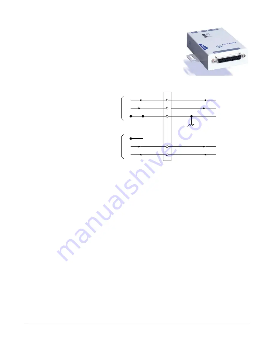
2
3
5
7
8
RD
TD
SG
SG
TD
RD
Radio
Data
Wayside
Data
Signal Ground
Receive Data
Transmit Data
Wayside Data to External
Device
Wayside Data from External
Device (Not Used)
Transmit Wayside
Data
Receive Wayside
Data
To PTX-PRO RS-232
Connector DB-9 (Male)


