Vision VR48 4 Series Скачать руководство пользователя страница 228

Vision VR48 Series 4 Router User Manual

228

© 2015 Vision Engraving and Routing Systems

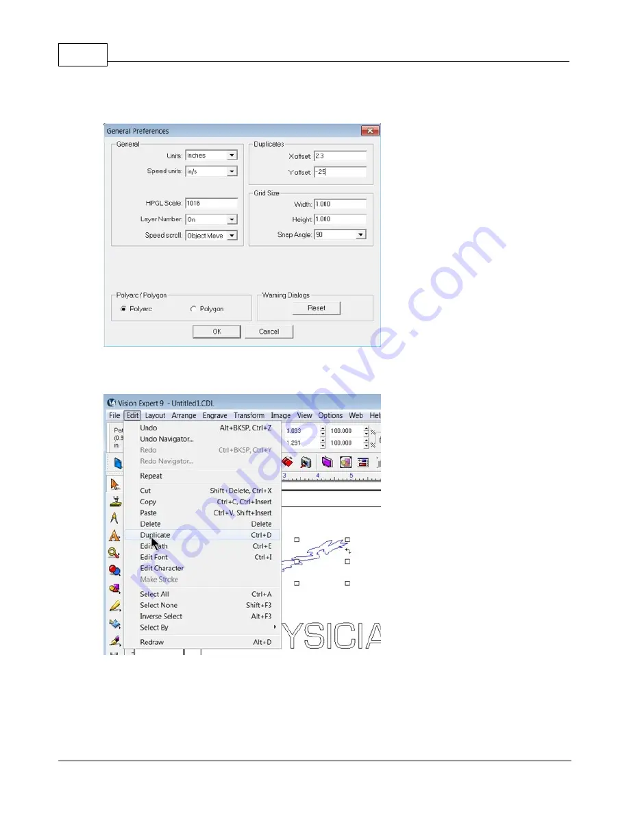
The General Preferences window will appear. In the Duplicate section, type in an X offset of 2.3 inches
and a Y offset of -0.25 inches. Click on OK to set these preferences.

To duplicate the selected image, either select Edit from the top menu bar and click on Duplicate, or use
the shortcut keys for this function CTRL D.

Содержание VR48 4 Series

Страница 1: ...2015 Vision Engraving and Routing Systems Vision VR48 Series 4 Router User Manual Revised 8 19 2015...

Страница 2: ...o claim to these trademarks While every precaution has been taken in the preparation of this document the publisher and the author assume no responsibility for errors or omissions or for damages resul...

Страница 3: ...y 26 7 Mounting the Pendant Holder Part III Series 4 Contoller and Vision 9 Software Installation 27 27 1 Computer Requirements 29 2 Direct Connection to Computer 36 3 Network Connection 39 4 Using a...

Страница 4: ...graving 152 Burnishing 154 Example Job 3 Burnishing 163 Profile Cutting 165 Example Job 4 Profile Cutting 177 2 Level 2 Job Examples 177 Reverse Engraving Color Filling 177 Example Job 5 Reverse Engra...

Страница 5: ...uting Systems 334 3 Motion System Cleaning and Lubrication 340 4 Vacuum Pump Maintenance Part XI Optional Accessories 342 342 1 UNIST Misting System 345 2 Vacuum Chip Removal System 346 3 Hold Down Cl...

Страница 6: ...aving software usage Some previous knowledge of engraving terms and the engraving process is certainly beneficial For information on the Vision Engraving Software see the Vision Engraving Software man...

Страница 7: ...mal use and service Upon written notification we will transfer the remaining warranty to a new customer This warranty shall cover all elements except for items covered by separate manufacturer s warra...

Страница 8: ...Extended Warranty the equipment will be in Lapse of Warranty An Extended Warranty can never again be purchased for any equipment that is in Lapse of Warranty It is the responsibility of the purchaser...

Страница 9: ...th low humidity and a minimum of dust Avoid placing the equipment in direct sunlight or in locations with excessive heat Do not expose the equipment to rain or use it near water You can clean the cont...

Страница 10: ...ent does not operate properly in particular if there are any unusual sounds or smells coming from it immediately unplug it and contact a service technician or your local distributor Unplug the machine...

Страница 11: ...occur to the operator If there are any questions about the abilities of your machine please call the Vision Engraving Systems technical support team at 602 439 0600 Do not force the machine to work at...

Страница 12: ...tons on the VR48 One is on each side of the gantry one is on the front panel and the last one is on the Pendant Refer to the below diagram and pictures to identify the emergency stop locations Users s...

Страница 13: ...Introduction 13 2015 Vision Engraving and Routing Systems...

Страница 14: ...bles ONLY 40 Amp 220 VAC 3 Phase will power the Vacuum Pump Mounting should be on Wall A and between 36 inches and 48 inches above the floor surface If locating the vacuum pump as shown Refer to Insta...

Страница 15: ...ft is required to remove the crate from the shipping truck and to locate the equipment in the building The forklift must have a minimum capacity of 6 000 lbs and 6 or longer forks 6 A pallet jack is r...

Страница 16: ...nstallation machine orientation to connect the router table vacuum pump motor and dust collector to the junction boxes and outlets 2 If an electrician is not available for the installation please call...

Страница 17: ...e left side of the VR48 Remove the cover and make the connections as shown below Ground is connected to the bare wire and common leads are connected to the two shielded wires The supply for this conne...

Страница 18: ...the fourth is to connect the Remote Start Switch for the Dust Collector System Plug the network cable or the crossover cable into the BOTTOM Ethernet port on the VR48 then either plug the network cab...

Страница 19: ...Collector Remote Start Switch will need to be connected For ease of operation a remote start switch and cables can be used to turn on the dust collector automatically when a job is being run The supp...

Страница 20: ...elow The input and output wires should be connected as shown Both input and output ground wires can be connected to the single GND location shown The switch can be wall mounted at a location convenien...

Страница 21: ...r cable when using the Engraving Head Spindle Port This port connects to the spindle cable and provides power and control signals to the High Frequency Router Head DACS Power Port Connects to the DACS...

Страница 22: ...Vision VR48 Series 4 Router User Manual 22 2015 Vision Engraving and Routing Systems 2 4 Installation Layout Diagram T Slot Table Models Example Router Installation Room Layout...

Страница 23: ...General Information Installation 23 2015 Vision Engraving and Routing Systems 2 5 Installation Layout Diagram Vacuum Table Models Example Router Installation Room Layout...

Страница 24: ...ump to the machine use the supplied 3 diameter vacuum hose and connect one end to the vacuum pump and the other end to the Main Vacuum Port on the machine The vacuum pump has been equipped with an ele...

Страница 25: ...mp and by viewing the direction of rotation through the motor fan cover and comparing it to the directional rotation indicators confirm the motor is rotating in the correct direction If it is not the...

Страница 26: ...g the Pendant Holder The Pendant Holder for the VR48 can be mounted on the front of the machine To install the Pendant Holder remove the three screws on the machine and mount the holder to the machine...

Страница 27: ...ork hub can be added to allow connection of the VR48 to your network The third configuration is for a connection from the computer to a hub or router and then to the VR48 This is WITHOUT a computer ne...

Страница 28: ...Vision VR48 Series 4 Router User Manual 28 2015 Vision Engraving and Routing Systems NECESSARY...

Страница 29: ...n the left side of the machine The safety key switch for the VR48 is located on the front left of the machine Turn the main power switch to On then turn the safety key switch to On Once the machine ha...

Страница 30: ...nd Routing Systems Locate the file named Start and double click on the file to start the installation The screen below shows Start exe but your computer might not show the exe portion Select Step 1 Se...

Страница 31: ...s 4 Contoller and Vision 9 Software Installation 31 2015 Vision Engraving and Routing Systems When the software is installed select Finish The Connectivity Manager will search for available Vision dev...

Страница 32: ...eless network card To set the computer s IP address open the Window s Control Panel Depending on how you have this folder set you will either see Network and Internet or you will see the Network and S...

Страница 33: ...aving and Routing Systems Then select Internet Protocol Version 4 TCP IPv4 Then select Properties Select Use the following IP address and enter 192 168 5 100 and set the Subnet mask to 255 255 255 0 a...

Страница 34: ...ems The IP address of the machine will need to be set to set up the connections properly Select the box next to the machine now listed in the Discover Machine Tools window to expand the information Th...

Страница 35: ...ems Set the IP address as shown to 192 168 5 101 then select OK This sets the machine s IP address The configuration is complete at this point Close the Discover Machine Tools window and return to the...

Страница 36: ...itch for the VR48 is located on the front left of the machine Turn the main power switch to On then turn the safety key switch to On Once the machine has initialized plug the supplied Vision USB drive...

Страница 37: ...aving and Routing Systems Locate the file named Start and double click on the file to start the installation The screen below shows Start exe but your computer might not show the exe portion Select St...

Страница 38: ...ftware is installed select Finish The Connectivity Manager will search for available Vision devices The configuration is complete at this point Close the Machine Tools Discovery window and return to t...

Страница 39: ...d on the left side of the machine The safety key switch for the VR48 is located on the front left of the machine Turn the main power switch to On then turn the safety key switch to On Once the machine...

Страница 40: ...nd Routing Systems Locate the file named Start and double click on the file to start the installation The screen below shows Start exe but your computer might not show the exe portion Select Step 1 Se...

Страница 41: ...s 4 Contoller and Vision 9 Software Installation 41 2015 Vision Engraving and Routing Systems When the software is installed select Finish The Connectivity Manager will search for available Vision dev...

Страница 42: ...ontrol Panel Depending on how you have this folder set you will either see Network and Internet or you will see the Network and Sharing Center immediately If you see Network and Internet select View N...

Страница 43: ...aving and Routing Systems Then select Internet Protocol Version 4 TCP IPv4 Then select Properties Select Use the following IP address and enter 192 168 5 100 and set the Subnet mask to 255 255 255 0 a...

Страница 44: ...ems The IP address of the machine will need to be set to set up the connections properly Select the box next to the machine now listed in the Discover Machine Tools window to expand the information Th...

Страница 45: ...5 101 then select OK This sets the machine s IP address The configuration is complete at this point The new IP address should appear in a few seconds in the Discover Machine Tools window Close the Dis...

Страница 46: ...User Manual 46 2015 Vision Engraving and Routing Systems 3 5 Vision Software Installation From the Main Installation Screen Select Step 2 Install Vision Software The Windows Installer will prepare th...

Страница 47: ...Series 4 Contoller and Vision 9 Software Installation 47 2015 Vision Engraving and Routing Systems Select Install The installation will proceed Select the appropriate language and select OK...

Страница 48: ...Vision VR48 Series 4 Router User Manual 48 2015 Vision Engraving and Routing Systems Installation will proceed Select Next to begin the installer Select Accept the license agreement then select Next...

Страница 49: ...Series 4 Contoller and Vision 9 Software Installation 49 2015 Vision Engraving and Routing Systems Select Next or change the destination folder not recommended Select Next to create the folder...

Страница 50: ...ide of this window by clicking in the box to the left of the machine or machine series you own The right side of the window will list a selection of Output Devices Only put a check mark in the box es...

Страница 51: ...Engraving and Routing Systems Select Continue to install True Type fonts and Vision Engraving Fonts on your computer The software will look for True Type fonts on your computer and allow the Vision s...

Страница 52: ...ems In this step the software will install any Engraving fonts on your computer When complete click on OK In order to install the fonts on the USB drive select A Removable drive and from the drop down...

Страница 53: ...e Installation 53 2015 Vision Engraving and Routing Systems Select OK to install to the default folder Select OK All fonts and clipart have been installed from the USB drive at this time Select OK to...

Страница 54: ...Vision VR48 Series 4 Router User Manual 54 2015 Vision Engraving and Routing Systems To complete the installation select Finish To close the Software Setup window select Finish...

Страница 55: ...of Vision 9 software Clicking on the Vision manuals link will give the user access to User Manuals Installation Guides Accessories and Training Videos If you were supplied with an Orange Dongle orange...

Страница 56: ...ads 4 1 High Frequency Router Head High Frequency Router Head Diagram Installed The High Frequency Router Head is NOT removable on the VR48 Router It is permanently aligned at the factory to a maintai...

Страница 57: ...Router Engraving and Knife Heads 57 2015 Vision Engraving and Routing Systems...

Страница 58: ...as an Engraving Head option that can be easily attached when the application requires There are two spindles available with the Engraving Head a standard spindle and a high speed spindle Standard Engr...

Страница 59: ...ocating pins which fit into holes on the router head Secure the engraving head with the supplied Allen screws Install the drive belt around the drive pulley and the driven pulley Connect the proximity...

Страница 60: ...meter for a 1 1 ratio and therefore turns the same RPM as the router motor The high speed spindle runs at a ratio of 1 833 1 When determining the RPM of the high speed spindle the user must multiply t...

Страница 61: ...It is a Spline Wrench DO NOT attempt to turn the set screw with any tool other than the cutter wrench Insert the cutter into the top of spindle and lower it until the cutter knob can be screwed into...

Страница 62: ...into the collet There are two sizes of collets included with your machine one for 1 4 inch diameter tool shanks and one for 1 2 inch diameter tool shanks The collet is held into the nut with a snap ri...

Страница 63: ...nough for your application WARNING Cutting tools are VERY sharp Handle cutting tools with extreme care Always use gloves when handling cutting tools to prevent injury To secure the tool in the collet...

Страница 64: ...Vision VR48 Series 4 Router User Manual 64 2015 Vision Engraving and Routing Systems To remove the cutter turn the nut as shown below using the open end wrench and spanner wrench...

Страница 65: ...the Rail Plate and align the mounting holes with those in the Rail Plate Install the 2 Mounting Screws and tighten the screws securely Plug the supplied cable not shown into the port on the top of the...

Страница 66: ...BLADES ARE VERY SHARP AND CAN CAUSE INJURY HANDLE WITH CARE PROTECTIVE GLOVES ARE RECOMMENDED WHEN INSTALLING OR REMOVING KNIFE BLADES To install a Knife Blade loosen the Allen Screw at the base of t...

Страница 67: ...home the machine and move the spindle over to a location near the middle of the table If using the Cutting Pad TURN ON THE VACUUM PUMP The vacuum pump must be running to pull the Cutting Pad and MDF B...

Страница 68: ...VR48 Series 4 Router User Manual 68 2015 Vision Engraving and Routing Systems Lower the spindle using the Z Down Key on the Pendant until the tip of the knife is approximately 1 inch above the Surface...

Страница 69: ...oscillating Hold the Surface Block down FIRMLY then press and HOLD the Set Surface Key down The spindle will slowly start to move down toward the Surface Block When the tip of the knife touches the Su...

Страница 70: ...ion Software The first step in creating cut files is to understand that the Oscillating Knife ONLY recognizes objects drawn in PEN 31 To create a custom pen using pen 31 in any color desired double cl...

Страница 71: ...uter S4 If this Device is not listed install this Device by closing the Cut Toolbox and selecting File Install Cutting Devices then selecting this Device from the list under options for your Vision Ro...

Страница 72: ...015 Vision Engraving and Routing Systems 5 Operation 5 1 The Pendant Controls The Pendant controls all of the movement and speeds of your Vision engraver or router Below is a picture of the Pendant Th...

Страница 73: ...ons control how fast the spindle will move down into the material Typically you can leave the speed at it s maximum setting unless you are engraving into hard materials such as acrylic or deep engravi...

Страница 74: ...manager When connected to Vision Machine Tools If there is no job in the machine pressing Shift then Start will display a list of jobs that are stored on the computer s hard drive Use the Y up and dow...

Страница 75: ...havepushedtheEmergency Stop Button you must twist the knob clockwise to release it Press the Goto Home button to power up the machine and move the spindle back to the home position The job you were ru...

Страница 76: ...Jog speed will determine how fast the spindle will move and the spindle position will be displayed on the Pendant screen as highlighted below Z Jog Buttons These will move the spindle up and down The...

Страница 77: ...sition d Press the Enter button to set this as the surface position The spindle will then move up to its lift position HINT It is sometimes easier to set the surface right before engraving the job To...

Страница 78: ...n The message Home Set will briefly appear on the Pendant screen This position is now set as the home 0 0 position To reset this home back to the machine s home position at the upper left lower left o...

Страница 79: ...ximity sensor on icon Proximity sensor off icon Spindle On Off Button The spindle motor can be either in automatic mode or off You can toggle between these two modes by pressing the Spindle On Off but...

Страница 80: ...Off Auto or Vac Off When set to Auto it will automatically turn on and off at the beginning and end of the engraving job If you press the PAUSE or STOP button the vacuum will turn off for safety reas...

Страница 81: ...ing the Numeric buttons then press the Enter button Press the Enter button one more time to jog the spindle to these coordinates or press Exit to cancel this operation Access Jobs Button When connecte...

Страница 82: ...eter of your itemtobeengraved Enter the diameter of theitemusingtheNumeric buttonsandpressENTER Note Thisbuttononly workswhenarotary axisis presentonyour machine Menu Button The Menu button allows acc...

Страница 83: ...e second menu page adds options for Digitize and DACS Those features are discussed in separate sections To access any of these menu items use the Y up or down arrows to highlight the menu item then pr...

Страница 84: ...Off Z Lift Height This will adjust the distance that the cutter lifts between characters whileengraving Movethe cursor totheZLiftHeightusingtheY upanddownjogbuttonsandpressEnter Usingthenumeric button...

Страница 85: ...ons to select the home position you would like to load Once the desired position is shown on the Pendant screen press the Enter button to load the home position The machine will now use this position...

Страница 86: ...Vision VR48 Series 4 Router User Manual 86 2015 Vision Engraving and Routing Systems The Configuration Menu There are three screens to the configuration menu as shown below...

Страница 87: ...d will allow the user to save various settings even when the machine is turned off The user can save settings such as the Spindle On Off Aux On Off Prox On Off Z lift Z depth RPM and surface location...

Страница 88: ...on that is set in the controller Use the Y up and down job buttons to select which parking position you would like to use then press Enter to select it Press the Exit button two times to return to the...

Страница 89: ...r Enter the Z lift setting with the numeric buttons then press Enter to save these settings To return to the main Pendant screen press the Exit button two times Run Self Test Pressing Enter with this...

Страница 90: ...eful tool that can be used to set up both the machine s home position and the plate size in the Vision 9 software To use this feature turn on the engraver and press the Go to Home button Open the Visi...

Страница 91: ...er Move the spindle over the material and position the laser pointer so that it is in the upper left hand corner of the engraving area you wish to define Then click on Next in the Measure Wizard windo...

Страница 92: ...t defined Follow the instructions on your machine or controller to have the machine outline this engraving area with the red dot laser pointer If the area appears to be correct click on OK in the Plat...

Страница 93: ...times easier to set the surface right before engraving the job To do this send a job to the machine to be engraved Press Pause Press Start The spindle will move to the first point to be engraved and p...

Страница 94: ...wn above 5 Press the Set Surface button on the Pendant 6 Press and Hold the Set Surface Button until the cutter tip touches the top of the Sensor Block The spindle will move down and stop when the cut...

Страница 95: ...ust set Non nose cone engraving depth control 1 Send a job to the Vision controller 2 Make sure that the spindle is locked by tightening the spring adjustment knob all the way down 3 Make sure that yo...

Страница 96: ...ition To reset the temporary origin back to the machine s home position at the lower left corner of the T Slot table press Shift then press Goto Home then press the Set Home button The red dot laser p...

Страница 97: ...en set up in the Vision 9 software select the Engrave icon from the left toolbar The Cut Toolbox window will appear and the top toolbar will change to the Engrave toolbar Make sure the Device is set t...

Страница 98: ...ystems Select the appropriate material from the Material Selection drop down list then select OK Verify the Cut Toolbox settings settings available will depend on device selected and version of Vision...

Страница 99: ...ownside to using tape is that it will remain on the table and can be a problem to remove A better solution is to place Multi Mat material on the table then place a piece of sacrificial material of the...

Страница 100: ...ther the standard edge guides shown below or custom edge guides can be ordered through Vision The standard edge guides are held in place with T nuts and screws and can be moved or removed as needed Th...

Страница 101: ...s from manufacturing that may restrict air flow It also will create a work surface that is truly flat in relation to the spindle Thicker boards provide less hold down but they can be fly cut more than...

Страница 102: ...n the front of the VR48 control which zone receives vacuum All valves are shown as closed The vacuum gauge displays the vacuum applied to the table Low vacuum readings can indicate air leaks or areas...

Страница 103: ...stems Plugs are used to block airflow in the vacuum ports that are not being used Remove the plugs in zones which are to be used Lay rubber strips in the vacuum table slots to concentrate vacuum in sp...

Страница 104: ...tion The Dust Collector system includes several components which need to be installed on the VR48 Install the dust collector hose support bar mount to the right side of the VR48 and mount the support...

Страница 105: ...e holes towards the front of the router head cover Lay the dust collector hose on top of the support plate and secure the hose using the hose brackets Use thumbscrews to secure the rear bracket to the...

Страница 106: ...outer User Manual 106 2015 Vision Engraving and Routing Systems NOTE The Hose Loop should provide enough length to allow the Gantry and Carriage to move to all 4 corners of the Table without excessive...

Страница 107: ...t file is installed on your computer with the Vision software and located in C Vision Express 9 Vision jobs or C Vision Expert 9 Vision jobs or C Vision Pro 9 Vision jobs depending on your version of...

Страница 108: ...wnload the newest version of Machine Tools from www visionengravers com in the Support Download Software Drivers and Utilities page Once Machine Tools is installed go to the folder named Dongle74 on y...

Страница 109: ...or StGigE Package_x64 exe for 64 bit operating systems If your computer asks if you want to run this file click on Yes or Run This file will install the driver needed to run the Ethernet DACS Camera G...

Страница 110: ...Vision VR48 Series 4 Router User Manual 110 2015 Vision Engraving and Routing Systems Right click on this shortcut and click on Rename then rename it to DACS...

Страница 111: ...ur machine and wait until it has initialized Press Go to Limits on the Pendant Make sure the 3 Ethernet cable and camera power cable also supplied are both connected from the right side of the router...

Страница 112: ...Systems DACS Connection Locations Electronics Box View Open the DACS VisionTool4 software using the newly created shortcut then select your machine in the Select Connection window and click on OK If t...

Страница 113: ...top menu bar and click on XMI Settings Select GigE_ST under Camera Settings as the Type After selecting the camera the following screen may appear If so select OK and then OK to close the XMI Setting...

Страница 114: ...router is being used For the VR48 Router Flip Image Vertical Rotate Image 0 The camera IP address must be set Select the Configure icon next to the Camera Type The following window will appear Note i...

Страница 115: ...Set IP Address at the bottom of this screen Type in the IP address as shown below and select OK Make sure you are using a STATIC IP Address and the recommended IP Address settings for your computer an...

Страница 116: ...ble then roughly center the camera over one of the fiducial markers using the X and Y move buttons on the Pendant It is best to use a graphic that contains both 0 25 inch diameter fiducial markers as...

Страница 117: ...It is possible that the camera s aperture is adjusted to over or under expose the image To adjust the aperture and change the amount of light entering the camera loosen the bottom thumbscrew on the c...

Страница 118: ...ugh contrast to view all image details then adjust the camera focus to show the image as clearly as possible To adjust focus first make sure the thumbscrew for the aperture adjustment has been tighten...

Страница 119: ...t or set any of the parameters scroll down and highlight the setting and press the Enter button on the Pendant There are two menu screens as shown below The Fiducial Diameter should be set to 0 25 To...

Страница 120: ...ision Engraving and Routing Systems The Retake Distance default value is 0 0000 and should not need to be changed The Settling Time default value is 200 and should not need to be changed Flip to Cut s...

Страница 121: ...t Jog Camera to Fid then press Enter to save this setting To set the Camera Scale first exit the Pendant s menu then press the Go to Limits button on the Pendant then press Set Home and then Enter Pre...

Страница 122: ...r almost touches the material then use the X and Y Arrow buttons to center the cutter over the fiducial marker as shown Press Set Home then Enter on the Pendant Press Go to Home then press Set Surface...

Страница 123: ...ndle should not turn on and it should not move down toward the material surface If this happens press Pause and Cancel Check to make sure the Spindle and Prox are turned off and restart this procedure...

Страница 124: ...ress Enter on the Pendant The Camera System will locate the fiducial marker When the fiducial marker has been found a blue box and cross hair will be displayed in the DACS software over the marker and...

Страница 125: ...ers click on either Vision Routers S4 2 x4 and smalle or Vision Routers S4 4 x8 and larger in the Manufacturer column Place a check mark in the box next to Vision DACS S4 or Vision Router DACS S4 in t...

Страница 126: ...Selected Device field then click on Setup Note if you have several machines please contact Vision Technical Support to set up individual folders for each device Select the Port tab then select Direct...

Страница 127: ...ey are placed along a common X or Y axis and at right angles to each other Note If the material is to be located on the table with the upper left corner of the material in the upper left corner of the...

Страница 128: ...99 and identifies those objects as Fiducials If you have drawn the Fiducials in the Vision software as 0 25 inch diameter circles follow the steps below to change the color pen of the Fiducials to Pen...

Страница 129: ...e this color swatch and exit the Edit Color window Now right click then left click on the new color swatch you ve just created to change both the outline and fill color to this new color named Fiducia...

Страница 130: ...ing and the remaining 3 Fiducials remained for the DACS software to use Create a tool path for the items you want to cut In this example a male tool path was created around the Vision logo Note that i...

Страница 131: ...he machine make sure you have selected the DACS driver for your machine This can be done by selecting the Plate Size icon on the top toolbar as shown or after clicking on the Engrave icon on the left...

Страница 132: ...essary so that the Machine Tools software sends the file to the correct machine Open the DACS software The DACS software icon should be on your computer s desktop When opening the DACS software you wi...

Страница 133: ...he job to the machine a good practice is to check that 4 procedures have been performed 1 Material Set The material is positioned at the top left corner of the table 2 Tool Set The proper cutting tool...

Страница 134: ...machine find the Fiducial Markers Once the Fiducial Markers have been located by the DACS software the machine will pause and any adjustments needed to properly position the tool path will be made au...

Страница 135: ...sensor Example jobs 6 7 and 8 can be performed with or without the Engraving Head as the set surface procedure is used The example jobs shown in this section show material placed in the UPPER LEFT co...

Страница 136: ...elow shows a spindle with a diamond drag cutter Spindle with Diamond Drag Cutter First to install the diamond drag cutter loosen the set screw on the cutter knob with the supplied cutter wrench and mo...

Страница 137: ...of engraving the Proximity Sensor is used and will sense when the cutter tip contacts the material then adjust the Z Axis height and cutting pressure automatically Also the spindle does not need to ro...

Страница 138: ...138 2015 Vision Engraving and Routing Systems The Plate Size window will appear Click on the Current Selection drop down list and select Custom Enter the plate size to be engraved for this example 3 x...

Страница 139: ...39 2015 Vision Engraving and Routing Systems your machine in the Selected Driver drop down list VE810 S4 shown To add text click on the Text Tools icon The flyout icons will appear then select the Tex...

Страница 140: ...ng to begin typing text Note that on the top toolbar the various font editing fields have appeared The user should become familiar with the various ways fonts can be formatted with the toolbar options...

Страница 141: ...gn Blank Center as shown below from the top toolbar Note that there are several ways to align objects within the Vision software The Break Text warning may appear If so select No If Yes is chosen and...

Страница 142: ...per left lower left on VR48 machines corner of the material positioned in the machine s home position Note that the Multi Mat material has been placed on the t slot table in order to hold the engravin...

Страница 143: ...inches 10 1 mm in the X and 0 55 inches 14 mm in the Y directions If the characters to be engraved extend beyond the machine s table size the file will not run because the motion system would have to...

Страница 144: ...Vision VR48 Series 4 Router User Manual 144 2015 Vision Engraving and Routing Systems on The Spindle icon on the Cut Toolbox is show below for reference Spindle icon shown as disabled...

Страница 145: ...you are ready to engrave select the Engrave icon from the left toolbar turn off the Dry Run option and check to make sure the Proximity Sensor see the Prox icon below is enabled then select the Engra...

Страница 146: ...146 2015 Vision Engraving and Routing Systems Make sure the material is positioned properly and secured on the engraving table then press the Start Button on the controller to begin engraving The fini...

Страница 147: ...il it is hand tight Then you must zero the cutter To do this you must first turn the micrometer so that the pointer points to 0 Note it is helpful to first turn the micrometer to the left clockwise un...

Страница 148: ...the material thickness This will cut completely through the material and potentially cut into the t slot table Press Start to resume engraving and to determine if the depth is appropriate For a detail...

Страница 149: ...will automatically be centered and have automatic Kerning In the below example Character Mode was selected from the top toolbar and the font was changed to Casual1 with a height of 1 250 inches and a...

Страница 150: ...s that the Vacuum Prox Dry Run and Spindle are all enabled Since this is the second example job sending a Dry Run job to the engraver is suggested Select the Engrave Icon to send the file to the engra...

Страница 151: ...s from scratching the surface of the material during operation and or getting trapped between the nose cone and the material when using the proximity sensor function and causing the engraver to not en...

Страница 152: ...of the cutter applied to the material Burnishing requires less pressure than other types of engraving and the EZ Rider attachment applies the proper amount of pressure for burnishing Installing the E...

Страница 153: ...hown on the Pendant screen can be used to view the Z position and assist in the pre loading procedure d Press the Enter button to set this as the surface position The spindle will then move up to its...

Страница 154: ...gle 7 85 x 5 4 inch 199 4 x 137 2 mm piece of coated brass also known as black brass or trophy brass The plate will use a text import function from an external text file that will be copied into a pla...

Страница 155: ...ght to 2 500 and 1 25 inches set the left margin to 0 175 inches and the top margin to 0 200 inches as shown then click on Apply Note that the page margins on the toolbar are located such that the top...

Страница 156: ...ems Click in the middle of the Plate Object Enter any text in the format you wish to use In this example two lines of text are entered as variables it does not matter what you type The text entered is...

Страница 157: ...text and double click on the font name If the size or other parameters need to be revised use the toolbar fields to modify the font style Please note that in this example the Width Compression for th...

Страница 158: ...fit width Method Width compress expand and Apply to Each Line Individually Deselect Word Wrap then select OK For a detailed description of all the font modifications possible refer to the Vision soft...

Страница 159: ...text and select copy from the edit menu or right click and select copy Note that in this example the two variables are entered as subsequent lines in the text file and that there may be difficulties...

Страница 160: ...ual 160 2015 Vision Engraving and Routing Systems Click in the center of the plate After clicking in the center of the plate all fields are merged and multiple plate objects will be created based on t...

Страница 161: ...grave icon from the left toolbar If you choose to run a Dry Run as shown to make sure the setup is correct proceed as in prior sections to send the file to the engraver Make sure you have performed th...

Страница 162: ...Vision VR48 Series 4 Router User Manual 162 2015 Vision Engraving and Routing Systems In this example the plate object lines were engraved...

Страница 163: ...djust the cutter to cut through the material PLUS 0 001 0 003 inches 0 0250 0 075 mm This method will produce a clean cut of the parts and lightly cut into the sacrificial material underneath or 2 adj...

Страница 164: ...we are cutting completely through there will likely be cut marks into the Multi Mat when the job is complete A better procedure is to use a piece of sacrificial material on top of the Multi Mat DO NO...

Страница 165: ...Vacuum Chip Removal System is highly recommended for this application and is shown in this example First the plate size will be adjusted to a 10 x 8 inch size the standard Vision VE810 10 x 8 inch ar...

Страница 166: ...manually on the toolbar or by selecting the object and clicking on a corner node holding down the left mouse button and dragging the corner to make the image smaller For this example the image was re...

Страница 167: ...text it does not matter what text is entered here It is just entered to create the text object To re size the text frame click and hold with the left mouse button on the black edge of the text frame a...

Страница 168: ...text fields shown and from the toolbar select Arrange Text To Graphics HINT to select more than one object click on the first object hold down the Shift Key then click on additional objects The two t...

Страница 169: ...nge can be performed after engraving To change the Plate Object frames to another color red in this example select the Plate Object frame then click on the Red color icon on the bottom toolbar of the...

Страница 170: ...Note that is there is more than one page of names each page of the file will need to have the plate frame color changed After changing the plate frame color If you try to send this file to the engrav...

Страница 171: ...Defaults then make sure Engrave by Color checkbox is selected then Apply and Close In order to send the engrave file to the engraver select the Engrave icon from the left toolbar at which time the Fi...

Страница 172: ...s Plastic Engraving is the material selected and all options are turned on in the Cut Toolbox including Dry Run for this example file Select the Engrave icon from the Cut Toolbox to send the file to t...

Страница 173: ...able and make sure the engraver is set up as in Rotary Engraving section before running the file Use the proper cutting tool for the engraving application Note that the nose cone for the vacuum chip r...

Страница 174: ...or window will re appear signaling that the software is ready for you to send another file to the engraver Since we need to change the material setting select Stop Cutting To change to the material se...

Страница 175: ...select Engrave from the Cut Toolbox The screen will show only objects in the color selected in the Filter by Color window The page selection screen will re appear for this example choose Current Page...

Страница 176: ...R48 Series 4 Router User Manual 176 2015 Vision Engraving and Routing Systems Note The Filter by Color screen will once again appear Since we have no further colors to send to the engraver select Stop...

Страница 177: ...tary Engraving section in Level 1 Job Examples 7 2 1 1 Example Job 5 Reverse Engraving In this example a sign will be made using reverse engraver s plastic The piece is pre cut and measures 6 inches x...

Страница 178: ...r we will add guidelines to the plate Right click outsize the plate area to show the Edit Guides window Then select the vertical guides as shown Enter 0 25 in the X entry field then click on Add Type...

Страница 179: ...are importing is BORD0117 and is located in the C Vision Express 9 ClipArt BORDER folder Select the file then click on Import Click inside the plate area to finish importing the file Change the size t...

Страница 180: ...t will separate the sign select the Shape Tools icon from the left toolbar then select the Rectangle tool Draw a rectangle 5 5 inches wide x 0 05 inches high and position it to 3 00 inches X and 1 90...

Страница 181: ...changed slightly once all the text has been entered Add the additional text as shown Each text is entered separately Monday Thursday is one line 8 00 5 30 is another line etc The guides we added can...

Страница 182: ...pacing between text lines was equalized by moving each line of text with the up or down arrow keys on the computer s keyboard Since we are engraving the back side of the plastic we need to mirror all...

Страница 183: ...the same outline color Select all objects then click on the Black color swatch on the bottom toolbar shown below with the left then the right mouse buttons This should be done any time clipart is imp...

Страница 184: ...Pro icon from the left toolbar and click on the Hatch Fill tool The top menu bar will change to the Hatch Fill toolbar in Vision Express only For Vision Expert or Pro see Fill Tool usage in Example Jo...

Страница 185: ...the engraving depth was set to 0 020 inches 20 clicks Send the job to the engraver using the Engravers Plastic material setting hook up your vacuum chip removal system and start the job When the engr...

Страница 186: ...ng a star object alignment and centering and tool path fills 7 2 2 1 Example Job 6 Deep Engraving This example job will cover the creation of a sign made from Sign Foam The background of the images wi...

Страница 187: ...Example Jobs 187 2015 Vision Engraving and Routing Systems Select the middle circle then select Transform Fit Text to Path from the top menu bar Select Add Text from the top toolbar...

Страница 188: ...ision Engraving and Routing Systems Select Arial Black from the font drop down list and set the size to 0 625 inches type in the text as shown then click on OK on the top toolbar Select the Bottom Sta...

Страница 189: ...he Apply button The text should now be located around the middle circle as shown below For this example the text needs to be placed in between the outside and the middle circles Enter 0 250 in the Tex...

Страница 190: ...Vision VR48 Series 4 Router User Manual 190 2015 Vision Engraving and Routing Systems The text should now be centered between the outside and middle circles Two stars will be added using the Star tool...

Страница 191: ...lick hold and drag the first star as shown To constrain the star and keep it level horizontally hold down the CTRL key on the computer keyboard while drawing the star Draw a second star in the locatio...

Страница 192: ...Vision Engraving and Routing Systems Select the first star then change the size to 1 25 inches high in the Object Height entry field on the top toolbar Repeat this for the second star Move each star t...

Страница 193: ...to Last Object and click on Center Vertically from the top menu bar To center these two stars within the circles first group the stars by selecting Layout then clicking on Group from the top menu bar...

Страница 194: ...e inner circle To align the group of stars to the circle select Layout Align and Distribute Align to Last Object and click on Center Vertically from the top menu bar Repeat this for Center Horizontall...

Страница 195: ...le the screen should appear as shown below We will now create a logo by welding text together Enter text using the Text Compose tool near the middle of the plate as shown The font used is HANDLED and...

Страница 196: ...ve it to the right using the arrow keys on your computer s keyboard Make sure there is an overlap with the next letter as pointed to below Add the second letter to the selected objects by holding the...

Страница 197: ...ving and Routing Systems Select all of the overlapped letters then select the Weld Tools icon from the left toolbar then select Basic Weld The finished logo should now appear as shown below Center thi...

Страница 198: ...d to graphics Select this text then select Arrange from the top menu bar and click on Text To Graphics as we did for the logo text To use the Make Path function select all objects Hint Press the F3 Ke...

Страница 199: ...ing to use a 1 16th inch End Mill to engrave out the background select the 1 16 End Mill as the Tool set the Depth to 0 150 inches Choose Red as the Color and set the Fill Style as Spiral and the Fill...

Страница 200: ...epth field as shown This will allow the user to set the number of passes the engraver will make The Engrave Parameters window will appear Set the number of passes to 1 Note that the other fields will...

Страница 201: ...u bar then click on Show Line Style Click off to the side of the graphic in an open area The image will then be displayed as shown below It is a good idea to zoom into several sections of the image to...

Страница 202: ...e select the Engrave icon from the left toolbar You will likely see this warning Click on OK Then select the Filter by Color icon in the Cut toolbox The Filter by Color window will appear Click on the...

Страница 203: ...s in the tool path we previously created we need to use the Set Surface feature on the machine Before doing so install the cutter so that the cutter tip extends MORE than the cut depth set in the tool...

Страница 204: ...nt then press Enter on the Pendant to set this as the surface position Using this method also protects the material from being scratched by the cutter Once the surface has been set select the Engrave...

Страница 205: ...e a dimensional letter will be cut out of 11 gauge aluminum plate The techniques used in this application are multi pass metal cutting holding down material creating tool paths and using the Surface S...

Страница 206: ...this example is Windsor and the font height is 8 inches In order to create a tool path text objects must be converted to graphics With the letter selected select Arrange from the top menu bar then cli...

Страница 207: ...In this case the material actually measures 0 091 inches thick We will set the cutting depth to 0 100 inches and choose the proper tool for this application Set the color to a different color than wha...

Страница 208: ...We only want to send the red tool path we created to the machine There are several methods to sending specific objects to the machine In this example we turn off all colors except for the one we want...

Страница 209: ...look like this This method of selecting which colors to send to the machine will be very useful when complex drawings with many objects colors and tool paths are used Before sending the job to the ma...

Страница 210: ...achine and click on the Tool Setup icon to change the settings to profile cut the aluminum based on the recommendations of the cutting tool manufacturer Feeds and speeds for profile cutting materials...

Страница 211: ...reated when cutting with a large diameter cutter A shop vac will be useful in keeping the work area and machine clean Remove the cut piece by prying it up with a sharp tool The spoil board will have g...

Страница 212: ...Vision VR48 Series 4 Router User Manual 212 2015 Vision Engraving and Routing Systems The finished part...

Страница 213: ...ill be cut out of Sign Foam material The techniques used in this application are cutting thick materials holding down material and creating tool paths 7 2 4 1 Example Job 8 Dimensional Letters in Non...

Страница 214: ...in the letter shown below The font used in this example is Arial Black and the front height is set to 8 inches In order to create a tool path we first need to change the letter from text to graphics W...

Страница 215: ...passes for this tool path The first thing you should notice is that it s not possible to set the number of passes to 1 This is due to a limitation in the standard End Mill settings In order to cut the...

Страница 216: ...a new name 1 8 End Mill 1 Cut was used in this example Enter the cutting Height of the tool 1 00 inch in this example Click on Add which stores the new tool in the tool library then click on OK Selec...

Страница 217: ...to 1 and click on OK then click on OK in the Male tool path window The tool path should now be created as shown below This example will show how to set the Device and the Tool before sending the job...

Страница 218: ...ng to the machine so put a check mack in the box to the left of Selected then click on Apply and then Close Select Engrave then Tool Options from the top menu bar Select Sign Foam Cutting from the Mat...

Страница 219: ...pply application tape to the back of the piece of sign foam It will not stick well enough to hold the material in place Once the material is held in place and the End Mill is installed in the spindle...

Страница 220: ...ou are ready to press the Emergency Stop or the Pause button on the Pendant in the event that the job was not set up properly and the cutter moves too far down and starts cutting into the machine s ta...

Страница 221: ...eating braille text reverse engraving profile cutting acrylic and applique material creating tool paths and color filling 7 3 1 1 Example Job 9 Acrylic ADA Signage Note 4 cutting tools are used in thi...

Страница 222: ...lowing warning about large radius corners may appear if so click on OK Our corner radius is small enough to not distort the rectangle The rectangle options menu will appear above the top toolbar Selec...

Страница 223: ...5 inch EURO Do not enter three separate lines of text by clicking three times with the ADA Raised Text tool Instead enter the first line of text press the Enter Key on you computer s keyboard the type...

Страница 224: ...ing Systems To insert some decorative clipart select the Clip Art Viewer after selecting Layout from the top menu bar The Clipart window will appear Double click on the folder named Decorative to open...

Страница 225: ...Vision Engraving and Routing Systems Select the STRIPE13 CDL file and click hold and drag it to the plate You will need to move these clipart images to their general locations within the plate area an...

Страница 226: ...more specific on the size of the clipart images select the image as shown then change the Object Width to 3 25 inches in the entry field on the top toolbar To rotate the image enter 20 in the Rotation...

Страница 227: ...now duplicate this image a specific distance from the original and make a total of 4 images To set the distance the duplicate image will be moved from the original image Select Options from the top m...

Страница 228: ...eferences window will appear In the Duplicate section type in an X offset of 2 3 inches and a Y offset of 0 25 inches Click on OK to set these preferences To duplicate the selected image either select...

Страница 229: ...clipart images Select all 4 images and move them roughly to the top center of the plate To accurately position these 4 images we need to group them Select Layout then click on Group Once grouped chan...

Страница 230: ...he second clipart image to 2 8 inches using the Object Width entry field on the top toolbar Move the second clipart image to the right side of the page In this example the position was roughly chosen...

Страница 231: ...Engraving and Routing Systems Select the group of images we created and the second clipart image To create a fill tool path for these images select the Tool Path Tools icon from the left toolbar and...

Страница 232: ...indow for this example choose the 030 Engraver as the Tool set the Depth to 0 010 inches set the Color to Red and set the Fill style as S sweep with a 20 overlap Click on the Depth options icon to set...

Страница 233: ...lose the Fill window and create the tool paths The clipart images now have tool paths which will be used to engrave out the centers of these images Two more tool paths need to be added First select th...

Страница 234: ...htly more than the material thickness in this case the material was 0 125 so the depth was set to 0 130 Set the Color to Green or another color you are not already using Click on the icon to set the n...

Страница 235: ...xample Jobs 235 2015 Vision Engraving and Routing Systems The tool path for the rectangle should be shown as below Select the ADA text then select Engrave then Create Tool Path and click on ADA Profil...

Страница 236: ...Depth to 0 035 inches and the Color to cyan or another unused color Click on the to set the number of passes Set the number of lasses to 1 then click on OK to close the Engrave Parameters window then...

Страница 237: ...ects Keyboard shortcut F3 and click on the Horizontal Mirror icon on the top toolbar With the drawing now mirrored we will turn off all colors except for red Hold the CTRL Key down on your computer s...

Страница 238: ...e sending any jobs to the machine place the material on the machine s table The material shown here is in black in the upper left corner of the picture Note When using the vacuum table all open areas...

Страница 239: ...ial method as described in the Level 1 Job Example for Profile Cutting The following lists the depth settings and applications for the tools used To set the depth of the 1 8 End Mill position the nose...

Страница 240: ...ation In order for the machine to insert the braille beads rasters into the drilled holes the braille inserter must be installed Install the inserter into its bracket Lower the inserter into the brack...

Страница 241: ...hen the inserter is at it s bottom position shown below Tighten the clamp to secure the inserter Lower the spindle until the tip of the inserter contacts your material and the depth pin is flush with...

Страница 242: ...Toolbox and run the job After the engraved areas are finished remove the flex cutter and install the 1 8 End Mill Set the micrometer back to its 0 point Turn on the Green color and turn off all the o...

Страница 243: ...ed we need to remove the cut out sign and flip it over to drill and install the braille raster beads Use a small sharp edged tool to carefully pry the cut out sign away from the vacuum table Flip it o...

Страница 244: ...irst turn on all colors in our Vision 9 plate again using the CTRL Left click on the color swatches and click on the Horizontal Mirror icon on the top toolbar to un mirror the plate Select Engrave fro...

Страница 245: ...the braille inserter by loosening the inserter clamp and remove the braille drill tool from the spindle Note that when lowered properly the inserter flange will be flush with the mounting bracket surf...

Страница 246: ...clicks Apply a piece of applique above the braille rasters as shown Press lightly to secure it with the adhesive Note that the applique has a pressure and time sensitive adhesive on the back side Appl...

Страница 247: ...Example Jobs 247 2015 Vision Engraving and Routing Systems Select Engrave from the Top Menu then click on ADA Plot Select Cut Raised Elements Click on the Engrave icon to send the job to the machine...

Страница 248: ...inished cutting the applique use a stiff bristled brush to remove any debris that remains in the cut areas then remove the excess applique and weed any remaining pieces from the centers of characters...

Страница 249: ...Example Jobs 249 2015 Vision Engraving and Routing Systems Mask the edges of the back of the sign and fill with an acrylic based paint The finished sign...

Страница 250: ...ogo creation welding objects object duplication creating a basic array dimensional placement of objects and the creation of a dial 7 3 2 1 Example Job 10 Plastic Control Panel The control panel create...

Страница 251: ...Arrange from the top menu bar and click on Text to Graphics Select the first character then using the arrow keys on the computer s keyboard move the letter to the right until it overlaps the second le...

Страница 252: ...overlap as shown Note that when overlapping letter like the letter S make sure that the side of the letter completely overlaps the next character With all letters selected select the Weld Tools icon...

Страница 253: ...n from the left toolbar then click on the Circle tool Click hold and drag a small circle Enter the circle radius of 0 75 inches in the Radius entry field on the top toolbar Also change the X and Y coo...

Страница 254: ...ting Systems Create another circle with a radius of 0 500 inches and place it at the coordinates of 1 900 X and 5 800 Y To create the array of circles a simple row in this case we first set the duplic...

Страница 255: ...the Y offset Click on OK to set this as the duplicate distance With the circle selected either select Edit then click on Duplicate from the top menu bar or press CTRL D on your computer s keyboard to...

Страница 256: ...nd Routing Systems Create another circle with a diameter of 1 00 inches and position it at coordinates of 5 05 X and 10 20 Y With this circle selected duplicate it to create a total of three circles U...

Страница 257: ...Routing Systems Create another circle with a radius of 0 25 inches and positioned at coordinates of 11 125 X and 10 20 Y We now add some rectangles to the plate Select the Shape Tools icon from the le...

Страница 258: ...the first row of circles Change the size and position of the rectangle to 2 inches wide x 1 inch high positioned at 2 40 X and 7 75 Y Change the Duplicate distance in the General Preferences window to...

Страница 259: ...ctangle near the lower left corner of the plate Change the size of the rectangle to 2 00 inches wide x 1 85 inches high and position it at 2 40 X and 10 20 Y We now add text under the logo we created...

Страница 260: ...dd it as a selected object To center the text under the logo either use the shortcut key by pressing the letter C on the computer s keyboard or from the top menu bar select Layout Arrange and Distribu...

Страница 261: ...SHIFT key on your keyboard then selecting the circle below it and either use the shortcut C on the keyboard or by using Center Vertically from the top menu bar Adjust the Duplicate distance within th...

Страница 262: ...s text above it To change the actual text over each circle double click on the text you wish to change select all of the text then type in the text as shown below Do this for the text over each circle...

Страница 263: ...he plate and add the text 0 12 and 24 as shown Add the text centered above the small circle as shown The positioning of these last two text entries was done visually Now we add text around the large c...

Страница 264: ...ht side of this toolbar Enter the text as shown The same font Helv1 sized 0 20 inches high was used To change the position of this text click on the Top Start Position icon on the top toolbar then cli...

Страница 265: ...and Routing Systems Duplicate this text Rotate the duplicate text 180 degrees using the Rotation tool on the top toolbar After entering 180 in the rotation entry field press the Enter key on the comp...

Страница 266: ...the text on the top of the circle group the two lines of text then center them both vertically and horizontally to the circle At this point we will need to write down the center position of the small...

Страница 267: ...en click on the Dial icon Before creating the dial set the Angle where dial starts as 300 degrees and the Angle where dial stops to 240 degrees Click in another entry field on the top toolbar such as...

Страница 268: ...nter key on the computer keyboard to set this radius Alternatively you can click hold and drag from the node near the top of the dial to adjust its radius although this is not an accurate way to size...

Страница 269: ...er of minor ticks to 1 set the Size to 0 125 inches and the Spaces to 2 Press OK to close this window Select the Labels and Major Tick setting icon on the top toolbar The Major Ticks window will appea...

Страница 270: ...ngraving Fonts as the Group choose Helv1 font from the Font drop down list then click on the Select button to the right of the Font drop down list Now set the Start number as 100 set the increment to...

Страница 271: ...enter coordinates that we wrote down a few minutes ago Select the dial and using the Horizontal and Vertical positions fields on the top toolbar enter the coordinates of 11 125 X and 10 20 Y The dial...

Страница 272: ...width of the cutter first select all the objects to be cut the objects shown in red above then select the Tool Path Tools icon from the left toolbar and since we are cutting from the inside of the se...

Страница 273: ...Depth per pass field and Last pass depth will automatically adjust to equal amounts In most cases when you first open this window these depth numbers will be incorrect therefore even if the number of...

Страница 274: ...and select the Tool Path Tools icon from the left toolbar then click on the Fill icon Set the tool as the 015 Engraver the Depth to 0 015 inches the Color to Black we will engrave this area at the sam...

Страница 275: ...Example Jobs 275 2015 Vision Engraving and Routing Systems Set the number of passes to 1 then click on OK Click on OK to close the Fill tool window...

Страница 276: ...ems Before sending this job to the machine all objects were selected press the F3 on your computer s keyboard to select all objects and grouped Then the objects were centered to the plate horizontally...

Страница 277: ...0 015 Flex Cutter was installed and a depth of 0 015 15 clicks was set on the micrometer The home position was set to the upper left lower left on VR48 machines corner of the material To send only th...

Страница 278: ...l Setup window and click on the Engrave icon in the Cut Toolbox Note that the material used here yellow is placed on top of MDF which is used as both a spoil board and a vacuum surface Any exposed are...

Страница 279: ...ghtly large than the final panel size we need to add one last item to our drawing Select the Shape Tools icon from the left toolbar and click on the Rectangle tool Draw a rectangle with a size of 13 7...

Страница 280: ...e the 0 015 Engraver as the tool and make the tool path color cyan or any other unused color You can then turn off the black and red colors using the color swatches on the right side of the Vision 9 w...

Страница 281: ...ting sound For routing applications one should start off using the recommended chip load and RPM for the material you are cutting Increase the feed rate until the part finish starts to deteriorate or...

Страница 282: ...Spindle is perfect for deep engraving into metals The high RPM allows cutters to stay sharp much longer for increased production and allows for much faster speed in engraving o The 3 25 HP 18 000 RPM...

Страница 283: ...he process whereby the software analyzes the bitmap image and determines how to represent the image with vector lines and curves Bitmaps are generally scanned into the computer with a scanner They can...

Страница 284: ...l be the Vision business logo The below image is the same file but zoomed in to see the individual pixels As you can see each pixel is a specific color and the edges are not smooth What we would like...

Страница 285: ...Pro 9 using the File Import command Vision Expert 9 can be used but not all of the same vectorization features are available For good quality vectorization the bitmap should be as large as practical I...

Страница 286: ...d to vectorize Select the Posterize Region icon from the top toolbar The below window will appear asking if you want to run the Prepare to Vectorize wizard Select Yes The wizard will open and recommen...

Страница 287: ...window will appear where adjustments can be made to the supersized bitmap The ideal settings will depend on the bitmap being used but it is best to try to adjust the image to create sharp crisp edges...

Страница 288: ...color The Brightness was reduced as much as possible without turning the entire area black then the Tolerance was increased until small speckles of black were seen around the image Then the Tolerance...

Страница 289: ...The top toolbar has many options for modifying the bitmap To keep this tutorial simply we will not cover all of the available tools and just select a preset for the type of image we wish to vectorize...

Страница 290: ...and Routing Systems Alternatively the preset can be adjusted by selecting the Trace Setup icon and making adjustments in the below window When a preset has been chosen or modified in the Trace Setup w...

Страница 291: ...o 291 2015 Vision Engraving and Routing Systems When the vectorization is complete select Close on the top toolbar Two images will now be on the screen Click hold and drag the top image away to expose...

Страница 292: ...ng and Routing Systems The vectorized image is shown selected in blue We can now modify the image to fix any errors or delete areas we do not wish to use In order to modify the individual elements of...

Страница 293: ...t individual elements to either modify the vector lines to more closely represent the original image or as in this case to delete sections of the image The outline of the entire image is selected belo...

Страница 294: ...can be applied to will appear as shaded areas as shown below The image is now ready to be used A note about accuracy It may have become noticeable that the vectorization process does not often create...

Страница 295: ...Vectorizing Images in Vision 9 Pro 295 2015 Vision Engraving and Routing Systems To use the Node Edit tool select a line to modify and double click on it Each node will appear as shown below...

Страница 296: ...Vision VR48 Series 4 Router User Manual 296 2015 Vision Engraving and Routing Systems To delete nodes and thereby straighten the line they are on click hold and drag a box around several nodes...

Страница 297: ...torizing Images in Vision 9 Pro 297 2015 Vision Engraving and Routing Systems Then press the Delete key on the keyboard to erase them You can also drag nodes and or lines to create a more accurate ima...

Страница 298: ...ed to a normal size the quality is improved If it is not possible to make the signature and an image must be used that has been previously scanned there is more image preparation required in order to...

Страница 299: ...99 2015 Vision Engraving and Routing Systems Select the image and make sure the image mode is set to RGB Select Image Mode RGB to change the image mode Open the Prepare to Vectorize Wizard by selectin...

Страница 300: ...elect OK and use the suggested file size The image will be resampled and the pixels will be split up into smaller pixels in order to increase the image quality Notice that with the default setting in...

Страница 301: ...ll be vectorized which is not desirable In this example the only setting that was changed was the Contrast which was changed from 0 to 70 Slide the contrast adjustment to the right to darken the signa...

Страница 302: ...e seen in the image above adjusted to 70 they are fairly light and will be eliminated in the next step After adjusting the contrast to 70 select OK The next Wizard window will appear In this window sp...

Страница 303: ...ndow will appear Click on the Down Arrow next to Pick color from shop palette and select the black color swatch P1 then click on OK Adjust the Tolerance as high as possible without going to 100 In the...

Страница 304: ...le In this example the Tolerance was reduced to 83 in this example The picture below shows that the speckles have been removed Note that the master brightness contrast and DeltaE settings at the botto...

Страница 305: ...Vectorizing Images in Vision 9 Pro 305 2015 Vision Engraving and Routing Systems The transformed image will now appear in the Vision 9 Pro window Note that it is completely black at this point...

Страница 306: ...es 4 Router User Manual 306 2015 Vision Engraving and Routing Systems Select the Center Line tool from the Accuscan icon on the left toolbar Marquee select the signature click hold and drag a box arou...

Страница 307: ...lbar Duplicate the settings of this example Select Centerline Trace only set Tolerance to Loose Speckle to 1 Resolution to 1500 Corner Sensitivity to 1 select the large pixel centering option to the l...

Страница 308: ...r The centerline vector will be created and by default the vector will be selected Move the vectorized image away from the original image to view the results It is common for the image to look slightl...

Страница 309: ...tion of the engraved product delete the original image and center the vector image in the plate Reduce the size of the image to represent an actual signature In this case the image was resized to 2 25...

Страница 310: ...to use and the depth you wish to engrave the item Choose the color for the tool path In this example a 0 015 Engraver was selected as the tool and the depth was set to 0 010 inches Then select OK Make...

Страница 311: ...e original scanned signature blue The line thickness of the vectorized image could be reduced by either using a smaller diameter cutter or reducing the depth of engraving The below image is a comparis...

Страница 312: ...umbers and lay them out in a specific array This section will demonstrate how the use can set up the software to create multiple jobs with multiple items and include the creation of serial numbers To...

Страница 313: ...he text added below will be fixed text and remain the same for all items engraved A 4th line of text is added using the same Text Compose tool but instead of clicking inside the plate to start the tex...

Страница 314: ...olbar then drag the BLUE frame outline down until there are two visible RED frames inside the blue frame These two red frames consist of an inner frame showing the area where the text will be constrai...

Страница 315: ...ext boxes and create the Alpha characters as fixed text the other option is to enter them all on one text frame and when creating the serial numbers choose only the numbers to change In this example t...

Страница 316: ...User Manual 316 2015 Vision Engraving and Routing Systems After aligning the text the plate is as shown below To begin creating multiple items select the text to be serialized and click on the Multip...

Страница 317: ...r of copies of the image to process as well as their location and spacing This is also where the text designated for serialization is chosen Note that the only text listed in the Replaceable items tex...

Страница 318: ...items we will be engraving The following diagram shows an array of parts placed in a template fixture and their locations spacing The X spacing of the parts is 5 00 inches and the Y spacing is 4 00 in...

Страница 319: ...atch on the bottom of the screen so we can differentiate it from the black text that will be engraved size it to 3 x 2 and center it to the plate using the Layout Arrange and Distribute Align to Sign...

Страница 320: ...n VR48 Series 4 Router User Manual 320 2015 Vision Engraving and Routing Systems To start creating multiples select ALL graphics and click again on the Multiples icon The Multiples window will again a...

Страница 321: ...of 5 00 Now reduce the Plate size in the Plate portion of this window to only allow 5 columns and two rows In this example the size was reduced to 12 inches height and 38 inches width This size MUST b...

Страница 322: ...the variable text first select the variable text it will highlight in blue in the Replaceable items text area then click on OK at the bottom of the page The Text Substitution window will appear Note...

Страница 323: ...ro 323 2015 Vision Engraving and Routing Systems Click on the column header where the variable text is displayed All rows will now be highlighted in blue and the Serialization box will be activated Cl...

Страница 324: ...Since we only want to produce 1 of each serial number set the Repeat field to 1 If we wanted to create more than one item with the same serial number we could enter the number of items we want to prod...

Страница 325: ...and will allow you to begin the next set of serial numbers where you left off Select Set as Start when producing the next set of serial numbers The Serialize window will now show the list of serial n...

Страница 326: ...then created Note that since we are making 30 items there are 3 pages to this job see lower right corner of the below picture In order to properly locate this array of text we now set the machine s h...

Страница 327: ...e machine using the Engrave by Color option If this is done keep in mind that if there are multiple pages of graphics as in this example 3 jobs will be sent to the engraver The 2nd job is held in the...

Страница 328: ...selecting the Engrave icon from the left toolbar the cut preview window is shown Two important things to remember are 1 make sure only the text is showing in this window and 2 look at the bottom righ...

Страница 329: ...below procedure to set a specific engraving depth for a specific color Setting Engraving Depth for a Specific Color For Online Engraving Only When sending graphics to the machine it is possible to as...

Страница 330: ...Verify that the changes have been made by hovering over the color swatch again with the mouse pointer All jobs sent to the engraver will now utilize the temporary depth and number of passes for the bl...

Страница 331: ...of chips reduces contamination and overheating in the spindle area The vacuum chip removal system also keeps the nose cone from skipping over letters when chips become trapped between the nose cone a...

Страница 332: ...per cooling of the electronics BEFORE OPENING THE ELECTRONICS BOX TURN THE POWER OFF TO THE MACHINE AND DISCONNECT THE MAIN POWER CABLE IF THE MACHINE S POWER CABLE IS HARD WIRED TO A JUNCTION BOX WIT...

Страница 333: ...ng and Routing Systems Router Head Air Filters To clean the router head air filters snap the filter guard off and remove the foam filter Clean per above instructions and replace before using the machi...

Страница 334: ...334 2015 Vision Engraving and Routing Systems 10 3 Motion System Cleaning and Lubrication Materials Needed Grease Gun with General Purpose Grease included Grease Fitting Adapter included Paper Towels...

Страница 335: ...e length of the router table To move the router head press on the left or right sides of the router head to move it left or right Use a paper towel to wipe down the Y Axis stainless steel rails Using...

Страница 336: ...paper towel to wipe down the X Axis stainless steel rails Using the included grease gun and grease fitting adapter supply grease to the grease fittings for the bearings ever 60 days Only 1 2 to 1 pum...

Страница 337: ...machine must be powered on Use the Z up or down controls on the pendant to move the router head Use a paper towel to wipe down the Z Axis stainless steel rails Using the included grease gun and greas...

Страница 338: ...w for cleaning Use a paper towel and wipe down the ball screw Using the included grease gun and grease fitting adapter supply grease to the ball screw grease fitting weekly 1 to 2 pumps of the grease...

Страница 339: ...arings and assemblies in your engraving machine are sealed and or coated using special low friction methods and should not be lubricated DO NOT attempt to lubricate the spindle or the spindle bearings...

Страница 340: ...d materials being processed Check the filter by removing the filter cap and filter on a weekly basis The filter can be cleaned by blowing compressed air from the inside of the filter outwards Care mus...

Страница 341: ...Pump Grease Fittings The Vacuum Pump requires periodic lubrication It is recommended to lightly apply grease via a grease gun to the two fittings shown every 3 000 hours of use Please refer to the Va...

Страница 342: ...fixtures or modifications to our standard accessories Please call us for details 11 1 UNIST Misting System The optional UNIST Misting System is designed to provide lubrication to the cutting tool and...

Страница 343: ...Optional Accessories 343 2015 Vision Engraving and Routing Systems...

Страница 344: ...ual 344 2015 Vision Engraving and Routing Systems UNIST Air Inlet Port Location Connect a compressed air supply regulated to 60 90 psi maximum to the UNIST Air Inlet Port The port is located on the le...

Страница 345: ...e area The vacuum chip removal system is designed to simplify the engraving process and minimize wear and tear on the engraver It uses a vacuum nose cone to remove chips created during the engraving p...

Страница 346: ...the clamp onto the T slot table surface and position it over the edge of the engraving stock The downward clamping force eliminates bowing This clamp can be used with material up to 1 4 thick Push Dow...

Страница 347: ...in most applications This clamp will hold material thicknesses of 020 032 062 and 125 by rotating the clamp and tightening a thumbscrew Corner Clamps This clamp is designed to hold down square or rec...

Страница 348: ...rized engravers and Pantographs These fixtures enable engraving on uniquely shaped items such as pens lighters knives keychains and more Universal Clamping Bars w Medallion Holder These clamping bars...

Страница 349: ...lions coasters paperweights dog tags and other round objects Usable with the Quick Lock or Versa Vise Adjustable Pen Fixture Enables engraving on most pens and cylindrical items that vary in diameter...

Страница 350: ...llion Fixture This is a double sided fixture that when turned in one direction accommodates a pen and when turned in the other direction accommodates a medallion seal or other circular item With a spa...

Страница 351: ...s specifically designed for T slot table users The cam type locking device allows for quick changing of parts This vise is supplied with a removable front clamping plate which allows for the holding o...

Страница 352: ......

Отзывы: