48
Printer Maintenance
Figure 9
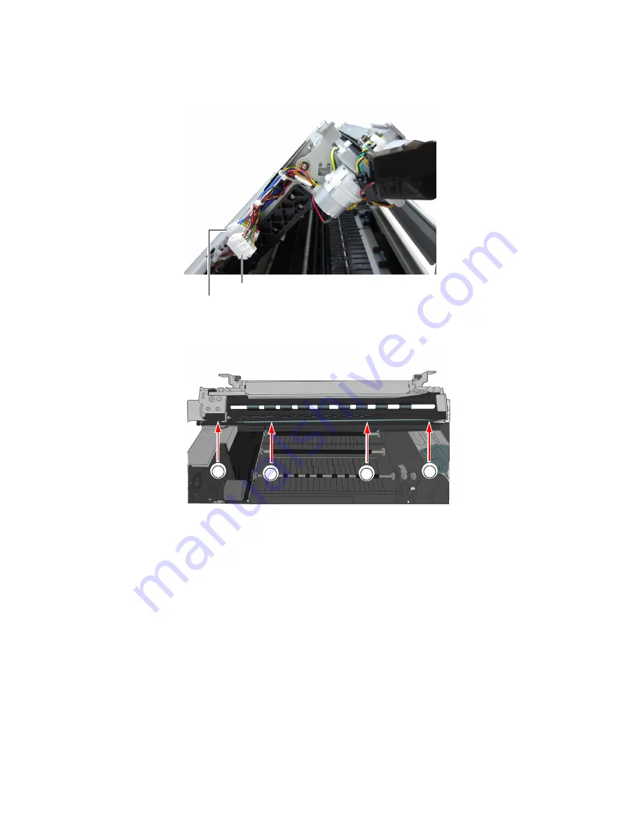
Connectors and cables on left side of clamshell
5. Use a T10 Torx driver to remove the four screws securing the output module.
Remove the outer screws (a) first.
6. Carefully remove the output module from the clamshell.
There is a black cable looped across the bottom of the output module. Gently pull
the cable away from the bottom corners of the output module and ease the output
module out.
The cutter assembly is now visible (
).
connector for output module
connector for cutter assembly
b
b
a
a
Содержание VP6 Series
Страница 1: ...U s e r G u i d e VIPColor VP6xx Printer Series ...
Страница 36: ...36 Using the Printer ...
Страница 58: ...58 Printer Maintenance ...


