VIPA IM 306-1LE00 Скачать руководство пользователя страница 45

Manual VIPA Accessories 

Chapter 4   Deployment


HB37E - IM - RE_306-1LE00 - Rev. 09/28 


4-11 

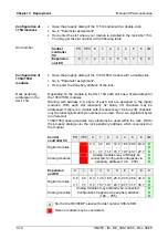
If activated the DP slave may react on a master failure or an interruption at 
the bus. 
If the DP slave is not responded by the master within the response 
monitoring time, the DP slave changes to safety state. 
Default value: activated 


Attention! 

Please regard, if you switch off the watchdog, the outputs of the appropriate 
DP slave may not be set to "0" in the event of an error. 
Consequently, it is strongly recommended that the watchdog is deactivated 
only during commissioning. 


Here the DP slave may more be commented. 


Here as "DPV1" is shown as interrupt mode. 
 
These parameters listed here serve exclusively for information and may not 
respectively must not be changed! 


If activated (enable) information are embedded to the diagnostics data, 
concerning the slot (module) an error has occurred. 
 
If activated (enable) information are embedded to the diagnostics data, 
concerning the error within the module an error has occurred. 
 
If activated (enable) information are embedded to the diagnostics data, 
concerning the channel error within the module an error has occurred. 
 
This parameter is only evaluated during deployment of analog modules and 
concerns how a value is stored in the CPU address area. 
In the 

Motorola-Format

 (default) the bytes are stored in descending 

significance, this means the 1. byte contains the high byte and the 2. byte 
the low byte. 
In the 

Intel-Format

 the value is turned and it is worked with ascending 

significance, this means the 1. byte contains the low byte and the 2. byte 
the high byte. 
 

Watchdog 


Comment 

Parameter 
assignment 

DP interrupt mode 

DPV1 interrupts, 
general DP 
parameters 

Device specific 
parameters 

Identifier related 
diagnostics 

Module state 

Channel related 
diagnostics 

Data format 

Содержание IM 306-1LE00

Страница 1: ...est Nr VIPA HB37E_IM Reference RE_306 1LE00 Rev 09 28 This manual is part of the documentation package with order number VIPA HB37E_IM and relevant for Product Order number as of state HW FW IM 306 DP...

Страница 2: ......

Страница 3: ...e verified with respect to the hard and software However we assume no responsibility for any discrepancies or errors The information in this manual is verified on a regular basis and any required corr...

Страница 4: ...tion required for the installation and the Profibus cabling Chapter 3 Hardware description Here the hardware components of the IM 306 DP slave are more described The technical data may be found at the...

Страница 5: ...sembly possibilities 2 2 Installation Guidelines 2 3 Profibus installation guidelines 2 6 Chapter 3 Hardware description 3 1 Properties 3 2 Structure 3 3 Technical data 3 5 Chapter 4 Deployment 4 1 Fa...

Страница 6: ...Contents Manual VIPA Accessories ii HB37E IM RE_306 1LE00 Rev 09 28...

Страница 7: ...e available in the manual an overall table of contents at the beginning of the manual an overview of the topics for every chapter an index at the end of the manual The manual is available in printed f...

Страница 8: ...vironments EX zone The manual must be available to all personnel in the project design department installation department commissioning operation The following conditions must be met before using or c...

Страница 9: ...er 1 Basics With this basics you get hints for the usage of the module After the description of the system conception you get basics concerning Profibus DP V1 Topic Page Chapter 1 Basics 1 1 Safety in...

Страница 10: ...causing the module to become inoperable or unusable Modules that have been damaged by electrostatic discharges may fail after a temperature change mechanical shock or changes in the electrical load O...

Страница 11: ...AG 115U is treated as a central controller which is to be connected via Profibus to a subordinate master system by means of the IM 306 DP slave In each rack besides the IM 306 DP slave only digital r...

Страница 12: ...interrupt capability this structure is to be used CPU IM IM IM CP IM 306 1LZ00 PW ER RD DE 64 32 16 8 4 2 1 1 0 PW ER RD DE 64 32 16 8 4 2 1 1 0 Master system CPU CP PW ER RD DE 64 32 16 8 4 2 1 1 0 I...

Страница 13: ...ecific diagnostic Profibus DP is a special protocol intended mainly for automation tasks in a manufacturing environment DP is very fast offers plug n play facilities and provides a cost effective alte...

Страница 14: ...hery and the high level master In accordance with the Profibus standards these devices have no bus access rights They are only allowed to acknowledge messages or return messages to a master when this...

Страница 15: ...ta transfer phase Before a DP slave is included in the data transfer phase the master checks whether the defined configuration corresponds with the actual configuration This check is performed during...

Страница 16: ...ctions for fast error localization Diagnostic messages are transferred via the bus and collected by the master DP V0 provides the basic functionality of DP including cycle data exchange as well as sta...

Страница 17: ...Slave 3 The DPM 1 Master Class 1 has the token and is able to send messages to or retrieve them from slave 1 then slave 2 etc in a fixed sequence until it reaches the last slave of the current list M...

Страница 18: ...le The Slot_Number 0 addresses data of the Profibus coupler Slot_Number 0 addresses the data of the function modules 0 1 2 3 5 Slot_Number Data structure 2Byte Output Modul 1 2Byte Output Modul 2 2Byt...

Страница 19: ...y the DPM 1 and is closely linked to the connection for cyclic data communication It can be used by the master which has parameterized and configured the respective slave Services for Acyclic data com...

Страница 20: ...dentified by an address This address must be an unique number in the bus and with the IM 306 DP slave between 2 and 125 At the IM 306 DP slave the Profibus address may be set by the address switch loc...

Страница 21: ...r 2 Assembly and installation guidelines In this chapter you will find all information required for the installation and the Profibus cabling Topic Page Chapter 2 Assembly and installation guidelines...

Страница 22: ...Master system CPU CP I O I O I O I O CC CC EU EU EU EU IM 306 1LE00 IM 306 1LE00 PW ER RD DE 64 32 16 8 4 2 1 1 0 In the following for the IM 306 1LE00 DP slave the possible slots at the racks are sho...

Страница 23: ...without interferencing the environment Each component of VIPA is developed for the deployment in hard industrial environments and fulfills high demands on the EMC Nevertheless you should project an E...

Страница 24: ...Analog lines must be laid isolated When transmitting signals with small amplitudes the one sided lying of the isolation may be favorable Lay the line isolation extensively on an isolation protected e...

Страница 25: ...the isolation one sided Then you only achieve the absorption of the lower frequencies A one sided isolation connection may be convenient if the conduction of a potential compensating line is not poss...

Страница 26: ...n isolated twisted pair cable based upon the RS485 interface The RS485 interface is working with voltage differences Though it is less irritable from influences than a voltage or a current interface Y...

Страница 27: ...ibus line has to be terminated with its ripple resistor Please make sure to terminate the last participants on the bus at both ends by activating the terminating resistor In systems with more than two...

Страница 28: ...vided with a switch that is used to activate a terminating resistor Attention The terminating resistor is only effective if the connector is installed at a slave and the slave is connected to a power...

Страница 29: ...09 28 3 1 Chapter 3 Hardware description Here the hardware components of the IM 306 DP slave are more described The technical data may be found at the end of this chapter Topic Page Chapter 3 Hardware...

Страница 30: ...xpansion units Supports digital and analog I O modules Profibus DP slave 9 6kbaud up to 12Mbaud Supports Profibus DP V0 and DP V1 Max 244byte input data and 244byte output data LEDs for bus diagnostic...

Страница 31: ...f LEDs which are available for diagnostic purposes on the bus and for displaying the local state With the following scheme they inform about the operating state of the DP Slave PW green ER red RD gree...

Страница 32: ...pin RS485 interface The RS485 interface has the following pin assignment Pin Assignment Bus termination 1 n c 2 M24V 3 RxD TxD P Line B 4 RTS 5 M5V 6 P5V 7 P24V 8 RxD TxD N Line A 5 4 3 2 1 9 8 7 6 9...

Страница 33: ...et Network topology Linear bus active bus terminator at both ends Medium Screened twisted pair cable under certain conditions unscreened lines are permitted Data transfer rate 9 6kbaud to 12Mbaud Tota...

Страница 34: ...Chapter 3 Hardware description Manual VIPA Accessories 3 6 HB37E IM RE_306 1LE00 Rev 09 28...

Страница 35: ...owing pages Further the DP V1 services and the diagnostics possibilities with Profibus are specified There is the possibility to establish a firmware update at the module For this the approach may be...

Страница 36: ...m CPU CP I O I O I O I O CC CC EU EU EU EU IM 306 1LE00 IM 306 1LE00 PW ER RD DE 64 32 16 8 4 2 1 1 0 Isolate the AG from the supply voltage With exception of the digital and analog modules remove eve...

Страница 37: ...your Profibus system Start your project engineering tool with a new project Configure a master system with a Profibus subnet For the project engineering of the IM 306 DP Slave choose the correspondin...

Страница 38: ...pply a green plug with CageClamp technology is deployed The connection clamp is realized as plug that may be clipped off carefully if it is still cabled Here wires with a cross section of 0 08mm2 to 2...

Страница 39: ...tal respectively analog modules are allowed Due to the data transfer via Profibus maximally 244byte of input data and 244byte of output data may be transferred The interrupt capability is only support...

Страница 40: ...the IM 306 1LE00 DP slave to the adaption module casing by snapping the module to the backplane bus by means of the left guide track Preset the Profibus address via the DIP switch at the front This ad...

Страница 41: ...are catalog Slave type GSD file DP V0 VI100BB4 GSD DP V1 VI110BB4 GSD Install the appropriate GSD file in your engineering tool For more information see the manual of you engineering tool Mount your P...

Страница 42: ...us interface of the DP slave may be accessed via this button Here you may assign a Profibus address to the DP slave and you may change the properties of the corresponding subnet If you have already as...

Страница 43: ...ded to the diagnostics data concerning the error within the module an error has occurred If activated enable information are embedded to the diagnostics data concerning the channel error within the mo...

Страница 44: ...the virtual slot 0 The Profibus interface of the DP slave may be accessed via this button Here you may assign a Profibus address to the DP slave and you may change the properties of the corresponding...

Страница 45: ...to the diagnostics data concerning the slot module an error has occurred If activated enable information are embedded to the diagnostics data concerning the error within the module an error has occurr...

Страница 46: ...ter Data Exchange BASP The DP slave remains still in Data Exchange and command output disable BASP is activated this means every output at the backplane bus are switched to 0 Data Exchange The DP slav...

Страница 47: ...IM 306 DP slave is connected to the DP master In the Siemens hardware configurator place the modules of the Siemens S5 rack in the plugged sequence starting with the 1 slot For this go to the Siemens...

Страница 48: ...ively 16 binary I O channels only the least significant byte numbers are used The more significant bytes are irrelevant 135U 155U analog modules may arbitrarily be used within the rack Within the prop...

Страница 49: ...may be addressed If there is a module with 8 respectively 16 binary I O channels only the least significant byte numbers are used The more significant bytes are irrelevant 135U 155U analog modules ma...

Страница 50: ...n establishment To access the DP V1 slave with the Siemens SIMATIC Manager the diagnostic address which can be set by properties is used as ID Using the following record set no as Index you get access...

Страница 51: ...related diagnostic Byte x x 8 Module status Byte max 40 x x 2 Channel related diagnostic Byte x x 11 Interrupt may be enabled or disabled via parameterization More detailed information about the stru...

Страница 52: ...le is connected which is not configured a connected module may not be accessed a module reports a diagnostic interrupt Bit 0 Entry for module at slot 1 Bit 1 Entry for module at slot 2 Bit 2 Entry for...

Страница 53: ...ta Bit 1 0 Module status module at slot 1 Bit 3 2 Module status module at slot 2 Bit 5 4 Module status module at slot 3 Bit 7 6 Module status module at slot 4 X 5 Bit 1 0 Module status module at slot...

Страница 54: ...0000 11111 Bit 7 6 01 Input Module 10 Output Module 11 In Output Module X 2 Bit 4 0 Error messages to Profibus standard 00001 Short circuit 00010 Undervoltage Supply voltage 00011 Overvoltage Supply v...

Страница 55: ...1 Bit 6 0 Type of interrupt 0000001 Diagnostic interrupt Bit 7 Code for interrupt x 2 Bit 7 0 Slot of the module that is producing interrupt 1 20 x 3 Bit 1 0 00 reserved 01 Diagnostic interrupt incomi...

Страница 56: ...e configurator with the configured DP slave Click on the DP slave and choose PLC Update Firmware This menu option is only available if you have a DP V1 configuration and the function Update firmware i...

Страница 57: ...iphery address 4 13 Power supply 3 4 4 4 Cabling 4 4 Variants 4 4 Profibus DP Addressing 1 12 Basics 1 5 Baud rate 2 6 Bus termination 3 4 Connectors 2 7 Data communication 1 7 Data consistency 1 7 Da...

Страница 58: ...Index Manual VIPA Accessories A 2 HB37E IM RE_306 1LE00 Rev 09 28 M Stich...

Отзывы: