


Chapter 4 Deployment
Manual VIPA Accessories
4-6
HB37E - IM - RE_306-1LE00 - Rev. 09/28
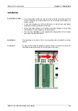
The installation happens with the following proceeding:
•
Isolate the AG from the supply voltage.
•
With exception of the digital and analog modules remove every module
from the rack.
•
Plug at the IM slot an adaption module casing, by hanging it up at the
upper edge, turning it downward and snapping it to the rack.
•
Fix the adaption module casing with its screws.
•
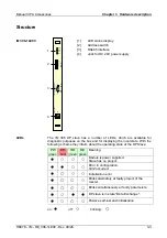
Plug the IM 306-1LE00 DP slave to the adaption module casing by
snapping the module to the backplane bus by means of the left guide
track.
•
Preset the Profibus address via the DIP switch at the front. This address
must be identical to the Profibus address you have preset during
hardware configuration.
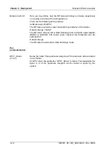
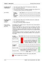
In the following for the IM 306-1UE00 DP slave the possible slots at the
racks are shown.
Possible positions are identified by X .
Rack
Slot
ZG CR 700-1
ZG CR 700-2
ZG CR 700-3
PS CPU
0 1 2 3 4 5 6 X
ZG CR 700-0
PS CPU
0 1 2 3 X
ER 701-1
0 1 2 3 4 5 6 7 8 X
ER 701-2
ER 701-3
0 1 2 3 4 5 6 7 X
ER 701-0
0 1 2 3 4 5 X
Proceeding
Slots in the
AG-115U
Содержание IM 306-1LE00
Страница 2: ......
Страница 6: ...Contents Manual VIPA Accessories ii HB37E IM RE_306 1LE00 Rev 09 28...
Страница 34: ...Chapter 3 Hardware description Manual VIPA Accessories 3 6 HB37E IM RE_306 1LE00 Rev 09 28...
Страница 58: ...Index Manual VIPA Accessories A 2 HB37E IM RE_306 1LE00 Rev 09 28 M Stich...