background image

VIP Vision Access Control Installation Guide - Version: VIPACC-Q219.1

26

3.2 Smart PSS Installation (continued)

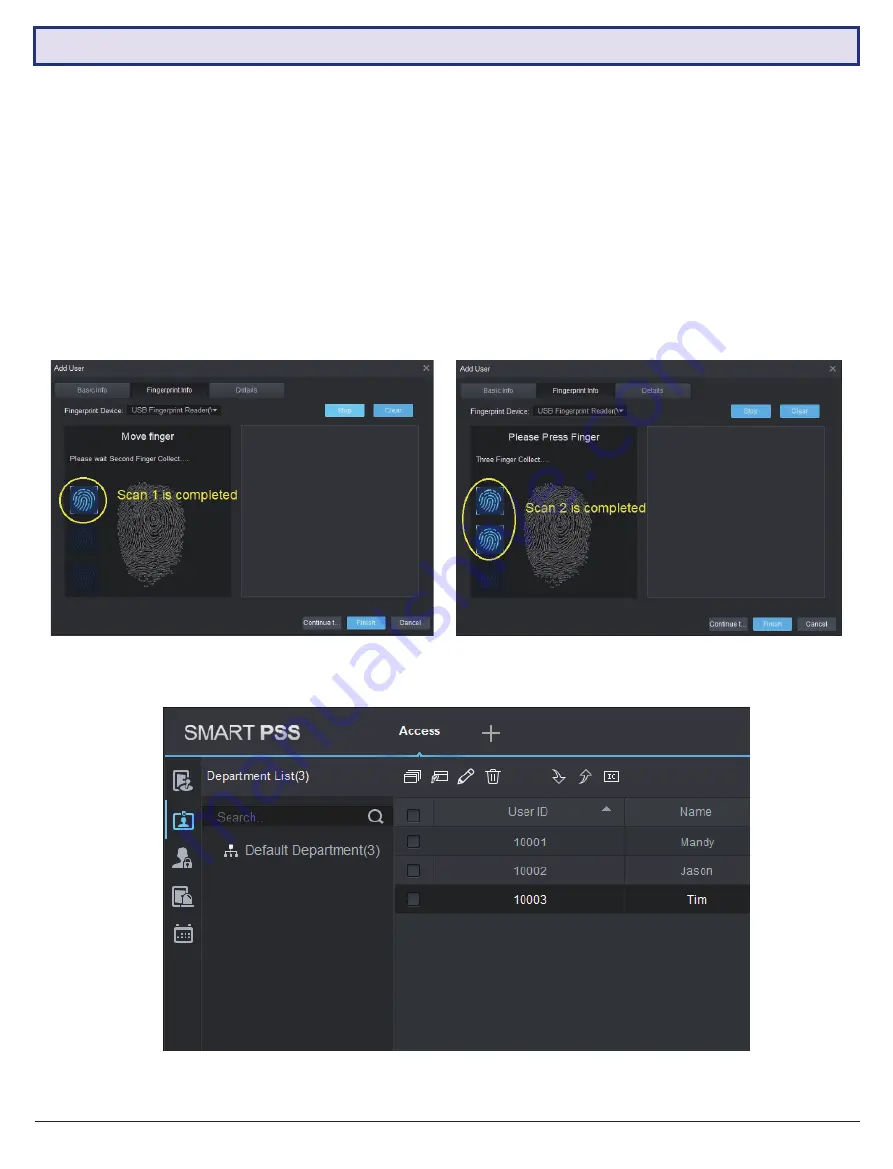
3.2.7  Add Fingerprints (optional)

Continuing from 

3.2.6 Add the Access Controller to Smart PSS

:

1.  Plug the USB Fingerprint Enrollment Reader to the PC USB port.
2.  In the Add User menu, click the Fingerprint info tab.
3.  Make sure “USB Fingerprint Reader” is selected in the Fingerprint Device section.
4. 

Place the user’s finger on the fingerprint reader and click the “Collect” button. For the most accuracy, ensure that 
the scanned finger is clean and not too dry or wet. When the blue fingerprint icon on the left appears, it means the 

scan is complete.

5.  For accuracy, the reader needs to scan 3 times. Repeat until the process is complete, then press “Finish”.

You will now see the user(s) added on the User Screen.

Содержание ACCON Series

Страница 1: ...ACCON Series AccessControlInstallationGuide Version VIPACC Q219 1 VIP Vision Professional Network Video Recorders...

Страница 2: ...y express or implied or upon any other basis of liability whatsoever even the loss or damage is caused by its own negligence or fault Seller does not represent that the products it sells may not be co...

Страница 3: ...2 3 8 Connect Network Cable 19 2 3 9 Connect Backup Battery 2P Series Only 19 3 Configuration via Smart PSS 20 3 1 Security Recommendations 20 3 2 Smart PSS Installation 21 3 2 1 Install the Smart PSS...

Страница 4: ...Requirements Notes IP Domain Name 192 168 0 2 User Name admin Password 123456 Maintenance password s4musvvcai 1 2 Factory Default Settings You must enter the correct IP Domain Name User Name and Pass...

Страница 5: ...on inputs Door open close status sensing inputs External alarm input s External alarm output s Internal alarms Door time out alarm intrusion alarm duress alarm and tamper alarm Emergency features All...

Страница 6: ...dicator Touch Keypad RFID Card Reader ACENR 2C Supports RS485 and Wiegand34 protocol RFID IC card Mifare Sensitive touch keypad with blue backlight Buzzer and Dual Colour LED indicator Touch Keypad RF...

Страница 7: ...40s Dimensions 120 x 76 x 18mm Touch Keypad RFID Card Reader ACKEY103 High Frequency 13 56MHz RFID Slim Dimensions 85 6 x 54 x 0 8mm Model ACLOC100 ACLOC101 ACLOC102 ACLOC103 ACLOC104 Image Type Mort...

Страница 8: ...VIP Vision Access Control Installation Guide Version VIPACC Q219 1 8 1 5 Access Controller Dimensions ACCON 2C41 ACCON 2P22 2P42 2P41 2P81...

Страница 9: ...net access please use another Ethernet port Communication between access controllers keypads and card readers requires CAT5e CAT6 cables This is to minimize errors Please install separate power supply...

Страница 10: ...No 3 4 doors unlock door sensor 4 External alarm input ALM IN output External alarm output OUT2 OUT2 5 DIP Switch Use for reset to factory default settings 6 Network cable input RJ 45 7 Card fingerpr...

Страница 11: ...Visit www vip vision com for full user manual and support 11 2 2 Wiring Diagrams continued ACCON 2P41...

Страница 12: ...VIP Vision Access Control Installation Guide Version VIPACC Q219 1 12 2 2 Wiring Diagrams continued ACCON 2P42...

Страница 13: ...Visit www vip vision com for full user manual and support 13 2 2 Wiring Diagrams continued ACCON 2P81...

Страница 14: ...ed type b Fail Safe type door lock connection Remove power to unlock Typical Fail Secure type door lock Electromagnetic locks drop bolts fail safe type It is strongly recommended to use separate power...

Страница 15: ...inputs are ACTIVE LOW i e connect to GND 0V to unlock the door All Door open close sensors inputs are also ACTIVE LOW i e when a door is closed the voltage on the corresponding SR input SR1 SR2 shoul...

Страница 16: ...VIP Vision Access Control Installation Guide Version VIPACC Q219 1 16 ACCON 2P42 2P81 ACCON 2P81 ONLY 2 3 Installation continued...

Страница 17: ...s The alarm inputs are ACTIVE LOW meaning when this pin is connected to GND 0V it will trigger the external alarm output relay s Note When ALARM1 input is pulled LOW all doors will be unlocked as long...

Страница 18: ...share one set of External Alarm output relay For 2P8 each External Alarm input has one External Alarm output relay ACCON 2P42 ACCON 2P81 External Alarm Input Relay External Alarm Output Terminal Bloc...

Страница 19: ...up The beep sound may last for 15 seconds when power is applied for the first time 2 3 8 Connect Network Cable Connect a CAT5e CAT6 LAN cable in the NET connector of the access controller panel Connec...

Страница 20: ...Login on Smart PSS Those using Smart PSS to view their system and on a computer that is used by multiple people should disable auto login This adds a layer of security to prevent users without the app...

Страница 21: ...e latest version of Smart PSS from the VIP Vision website at www vip vision com support downloads Must check the accept agreement box Check both boxes for complete software installation Change the ins...

Страница 22: ...ss Controller is 192 168 0 2 You must change the PC network card IP address to this subnet i e you must set the IP of the PC network card to 192 168 0 xx where xx is a number from 0 to 255 other than...

Страница 23: ...roller to Smart PSS 1 Open Smart PSS and log in 2 The program will open to the Devices menu Click the Add button 3 In Manual Add enter IP Domain Name 192 168 0 2 User Name admin default Password 12345...

Страница 24: ...may not match up with the actual time 1 Drag the mouse to the Devices menu item on the top left of the Add Devices screen and click the X symbol to exit to the Main Menu 2 Click the Device CFG icon t...

Страница 25: ...be read out automatically Remove the card when you see the card number Card Type Select the user level Card Password Not applicable Unlock Password enter a 6 digit keypad password for this user All u...

Страница 26: ...erprint info tab 3 Make sure USB Fingerprint Reader is selected in the Fingerprint Device section 4 Place the user s finger on the fingerprint reader and click the Collect button For the most accuracy...

Страница 27: ...then Access Level to enter the Access Level screen 2 Click the Add button 3 Enter the name for the Door group the time zone and the doors that the users belonging to this group can gain access to In...

Страница 28: ...oller menu click the Upload User to Device icon and then Timezone to enter the Time Zone Setup screen 2 Click the Add button then enter the name of the time schedule Press the Settings button on the r...

Страница 29: ...e Upload User to Device icon and then Holiday to enter the Holiday Schedule Setup screen 2 Click Add then enter the name of the holiday schedule Select the date and click Save when finished 3 Set the...

Страница 30: ...S Installation continued 3 2 10 Set Holiday Schedules continued 4 Select which doors to restrict access to through Door Configuration 4 Select the Holiday Timezone then click OK when done In this exam...

Страница 31: ...ss Level screen 2 Click the Add User icon 3 When the User Select dialog box pops up select the user s department from the drop down list and click OR enter the user s ID or name directly You may also...

Страница 32: ...e box Door Name of the door Reader1 Name of the entrance reader Reader2 Name of the exit reader Status Normal Always Open Always Close Unlock hold interval The time that the relay stays unlocked Close...

Страница 33: ...og Files VIP Vision access controller supports up to 150 000 log records The records can be exported for data analysis 1 Click the Log icon on the side menu then click the Export button A dialog box w...

Страница 34: ...by appointed users before other users with lower access rights can For example a shop manager must open the door earlier than the shop workers to make sure that the manager is in the shop when other w...

Страница 35: ...s 1 Click the Upload User to Device icon then select Multi card Unlock 2 A user group must be added first Click User Group to create one 3 Click the symbol to add a user group 4 Name the user group 5...

Страница 36: ...Number of users per group requires to Multi Unlock in our example one user per group 12 Once set up is finished you will see the following screen You can enable or disable this function with the swit...

Страница 37: ...t use the exit door An example for this application is a car park 1 First click the Upload User to Device icon then select Anti passback 2 Click the Add button 3 Select a Device the name of the access...

Страница 38: ...ortant For this function to work properly Door Sensors must be enabled in the Door Configure menu 1 Click the Upload User to Device icon then select Inter door Lock 2 Click the Add button 3 Select a D...

Страница 39: ...here high security is needed Important Once this function is activated the door must be opened MANUALLY after verification Entering the keypad password or tapping card on the card reader will no longe...

Страница 40: ...AM in this case and select the camera to be displayed 9 Make sure the switch Auto Open Video is on Blue colour and click the Save button to finish Remote verification setup is now complete In this exa...

Страница 41: ...r Configuration 3 Following the image below turn on the Door Alarm and Door Sensor switches set a Close Timeout time example 10 seconds and select the Overtime check box 4 Click OK to save 5 Click the...

Страница 42: ...rance Network Camera will display the user who taps the cards at Door 1 The actions when an event occurs are to Link Video and generate alarm sound in PC speakers To enable the event you must enable t...

Страница 43: ...triggered when verification of current period is not in holiday period Incorrect first card Alarm is triggered when a door is not unlocked by the first card user first Inter lock mode Alarm is trigger...

Страница 44: ...bolts and the access controller Ensure that jumpers on the access controller main board are set correctly Check door lock power User added but cannot gain access Ensure that the user has assigned acce...

Страница 45: ...rtunately you must set up User rights and Access Levels etc again after reset to factory settings Although you can see the user information and access levels on the PC these information has not downlo...

Страница 46: ...options so we do not use IC cards in our new designs and products Can I Inter lock Anti passback doors connected to different access controllers that are in the same network No Inter lock Anti passba...

Страница 47: ...tting the IP address back to 192 168 0 2 4 2 Frequently Asked Questions continued 1 Click the Device CFG icon on the main menu 2 Click the access controller s name 3 Click Network and then TCP IP 4 En...

Страница 48: ...e All products designs and software here are subject to change without prior written notice Please visit our website for more information For more information please visit Version VIPACC Q219 1 Access...

Отзывы: