


SW2
SW1
3
1
2
JP
Connector Pin
3
1
2
JP
ON
1
2
3
4
5
6
SW2
ON
1
2
3
4
5
6
7
8
9
10
SW1
JP
3
1
2
120
Ω
terminal resistor is
connected on RS485 Bus
120
Ω
terminal resistor is
connected on RS485 Bus
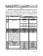
Protocol Select Speed Dome Address Select
Vertical view
Figure 2
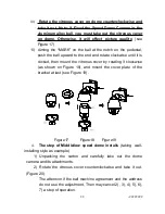
b.
Middle speed and low speed dome
ON
1
2
3
4
5
6 7
8
9 10
SW1
SW 2: DIP1--DIP 4 Proocol Select
SW2: DIP5 --DIP 6 Baud Rate Select
JP
3
1 2
3
1 2
JP
Address Select
120
Ω
connected on RS 485 Bus
terminal resistor is
120
Ω
connected on RS 485 Bus
terminal resistor is
ON
1
2
3
4
5
6
SW2
Protocol Select
Bracket for fixed camera
Figure 3
As shown in Figure 2,3, SW1 is used to set address of the dome
camera from 1 – 1023. The coding switches from DIP-10 to DIP-1
are equivalent to a 10-bit binary digital. DIP-10 is MSB while DIP-1
is LSB. The state “ON” of each bit means 1 while “OFF” means 0.
Following table shows states of coding switches of some
addresses.
Dome
Address
States of Coding Switches
DIP-1
DIP-2
DIP-3
DIP-4
DIP-5
DIP-6
DIP-7
DIP-8
DIP-9
DIP-10
1
ON
OFF
OFF
OFF
OFF
OFF
OFF
OFF
OFF
OFF
2
OFF
ON
OFF
OFF
OFF
OFF
OFF
OFF
OFF
OFF
3
ON
ON
OFF
OFF
OFF
OFF
OFF
OFF
OFF
OFF
-14141414
14
Содержание VC-EX861
Страница 41: ...37373737 37...
Страница 42: ...CCTV SYSTEM...


