17
Never
interchange cores
"L1" and "N".
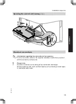
■ Install an isolator in the power
supply line that simultaneously
isolates all non-earthed conduc-
tors from the mains with at least
3 mm contact separation.
We additionally recommend
installing an AC/DC-sensitive
RCD (RCD class B
) for
DC (fault) currents that can occur
with energy-efficient equipment.
Remove the existing cable grom-
met when using larger cross-sec-
tions (up to
7
14 mm). Secure the
cable with cable grommet
F
(see
page 18) integrated into the cas-
ing base.
■ Max. fuse rating 16 A.
gD
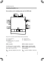
External safety solenoid valve
(LPG)
D
Do
not
remove jumper between "1"
and "L" when making this connec-
tion.
lH
Power supply of accessories
Where the boiler is installed in a wet
area, the connection of accessories
to the power supply must not be car-
ried out at the control unit. The
power supply connection for acces-
sories can be made immediately at
the control unit, if the boiler is instal-
led outside wet areas. This connec-
tion is controlled directly with the
system ON/OFF switch (max. 3 A)
■ Vitotrol 100 UTA
■ Vitotrol 100 UTDB
■ Vitotrol 100 UTDB-RF
Low voltage plug X3
!
Outside temperature sensor (only
for weather-compensated control
units)
Installation:
■ North or north-western wall, 2 to
2.5 m above ground level; in multi-
storey buildings, in the upper half
of the second floor
■ Not above windows, doors or ven-
tilation outlets
■ Not immediately below balconies
or gutters
■ Never render over
■ Cable length max. 35 m with a
cross-section of 1.5 mm
2
?
Flow temperature sensor for low
loss header (accessories)
%
Cylinder temperature sensor (fitted
and connected)
aVG
KM BUS subscriber (accessory)
■ Vitotrol 200A or 300A remote
control (only for weather-com-
pensated control units)
■ Vitocom 100
■ Extension kit for one heating cir-
cuit with mixer (only for weather-
compensated control units)
■ Extension EA1 or AM1
Installation sequence
Electrical connections
(cont.)
5457 552 GB
Installation

