background image

11

Mit der Ösen-Biegezange (4198) von Viessmann 

können Sie auch die Fahrdrahtlängen bzw. Ma-

stabstände indviduell Ihrer Anlage entsprechend 

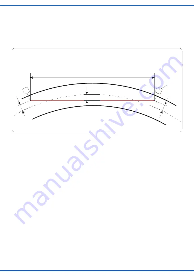
festlegen. Der maximale Mastabstand ist vom 

Gleisbogenradius R und der Seitenabweichung 

des Fahrdrahtes S abhängig. Er kann nach fol-

gender Formel errechnet werden:

With the eye hook bending pliers (4198) from 

Viessmann you can adjust the length of the cate-

nary wires or the distance between the masts to fit 

your individual layout. The maximum distance is 

depending on the radius of the track curve R and 

the sideways deviation of catenary wire S. It can 

be calculated with the following formula:

L max. = 4 x  

√ 

R x S 

Die Seitenabweichung S darf nach NEM 201 für 

die Spurweite H0 maximal 6,5 mm, für die Spur-

weite TT maximal 4,5 mm und für die Spurweite N 

maximal 3,5 mm betragen. Dieser Wert ist ein Be-

triebsgrenzmaß, das Sie nur im Bogen voll nutzen 

können, auf den Geraden bei einer Zick-Zack Ver-

legung sollen nur 2/3 dieses Wertes genutzt wer-

den.
Die Fahrdrähte der Viessmann-Oberleitung sind 

lötbar und somit auch mit vorhandenen Oberlei-

tungen verknüpfbar.
Zu beachten ist, dass die entsprechenden Be-

reiche der Fahrdrähte vor dem Verlöten entfettet 

werden müssen (eventuell mit handelsüblichem 

Spülmittel).

L max. = 4 x   

√ 

R x S

The sideways deviation S may have a maximum 

of 6.5 mm for the H0 track width, a maximum of 

4.5 mm for the TT track width and a maximum 

of 3.5 mm for the N track width in accordance to 

NEM 201. This value is the operating limit that can 

only be fully used in the track’s curve. While on 

the straight segments in the zigzag design, only 

2/3 of this value should be used.
The catenary wires of Viessmann’s catenary  

system can be soldered and so they are attach- 

able to existing catenary systems.
Please take care that corresponding areas of the 

catenary wires have to be degreased before sol-

dering, you could use normal commercial wash-

ing-up liquid.

S

S

S

L

Mast mit 

Ausleger

Mast with 

beam

Fig. 13

Abb. 13

Verwendung der Formel zur Berechnung des  

maximalen Mastabstandes

Using the formula for calculating the maximum distance  

between the masts

L = Fahrdrahtlänge/

catenary wire length

R = mittlerer Gleisbogenradius/

middle radius of curved track

S = Seitenabweichung/

lateral deflection

Содержание 4100 H0

Страница 1: ...ration Manual Startset Oberleitung Start set catenary system 4100 H0 4200 TT 4300 N 1 Wichtige Hinweise 2 2 Einleitung 3 3 Montage 4 4 Gew hrleistung 12 1 Important information 2 2 Introduction 3 3 Mo...

Страница 2: ...ahrdr hte 89 mm 4330 6 Fahrdr hte 222 mm 4331 1 Fahrdrahtmontagelehre 4396 1 Important information Please read this manual completely and attentive ly before using the product for the first time Keep...

Страница 3: ...r Mitte des Gleisbogens abweicht Da mit wird verhindert dass der Pantograph bei Elek trolokomotiven mit einer besonders orginalge treuen Pantographenausf hrung vom Fahrdraht abrutscht 2 Introduction T...

Страница 4: ...e base mount 2 Schieben Sie die Streckenmasten von den Grundtr gern herunter 2 Slide the masts down from the base mounts Roco LINE mit Bettung alt Roco LINE Piko A GleisM rklin K Gleis Fleischmann Mod...

Страница 5: ...H0 Example construction of the catenary system H0 6 Markieren Sie mit Hilfe eines Stiftes oder ei ner Spitze die Schraubenposition Anschlie end entfernen Sie den Grundtr ger und stechen bzw bohren mi...

Страница 6: ...side on the lower beam depending on the layout of masts Lage des Fahrdrahtes bei Montage des Streckenmastes im Au enbogen Position of the catenary wire with the masts in the outer curve Lage des Fahrd...

Страница 7: ...ounterpressure to the beam the eyelet latches onto the lower beam On the upper beam the eyelet can be slid lengthwise travel direction on the beam to compensate for the differences in length Fig 8 Abb...

Страница 8: ...rleitung oder des Pantographens vermeiden Besondere Hinweise Sollten Sie abweichend von den in der Montage anleitung zugrundegelegten Gegebenheiten die Oberleitung einsetzen geben wir folgende Emp feh...

Страница 9: ...on 620 mm vorgefertigte Fahrdrahtl ngen angeboten Um die entsprechende Position des Strecken mastes zu ermitteln empfehlen wir die Mastpositi onslehre H0 Art Nr 4197 TT Art Nr 4297 oder N Art Nr 4397...

Страница 10: ...mit Ausleger 35 4 mm from the middle of the tracks for tensioning masts with cantilever 34 mm Abstand zur Gleismitte f r alle Streckenmasten 34 mm from the middle of the tracks for common masts 37 5...

Страница 11: ...eitung sind l tbar und somit auch mit vorhandenen Oberlei tungen verkn pfbar Zu beachten ist dass die entsprechenden Be reiche der Fahrdr hte vor dem Verl ten entfettet werden m ssen eventuell mit han...

Страница 12: ...t version of the manual can be looked up at the Viessmann homepage using the item No 4 Gew hrleistung Da wir keinen Einfluss auf den richtigen Aufbau haben k nnen wir aus verst ndlichen Gr nden bei Ba...

Отзывы: