background image


6


SECTION VIEW DRAWING AND DESCRIPTION –
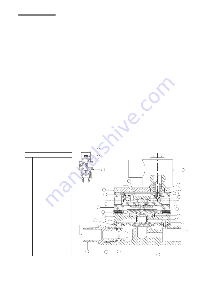
SERIES 79N ELECTRIC/PNEUMATIC ACTUATOR


The Series 79N Electric/Pneumatic Actuator is a single-
unit device used in the actuation of Series 758 Preaction
Valves with double-interlock electric/pneumatic trim.

Diaphragms separate the Series 79N into four chambers.
The upper and upper-middle chambers control the
actuation, while the lower and lower-middle chambers
act as the water control valve.

During system charging, air pressure enters the upper-
middle chamber of the Series 79N. Pulling up on the auto
vent, which is located on the Series 79N trim, sets the air
pressure in this upper-middle chamber. Water supply
pressure from the piston charge line enters the upper
chamber, and the normally closed solenoid, which is built
into the Series 79N, sets this water pressure. 


There is no

need to activate the solenoid in order to set the
system.


The system air pressure in the upper-middle chamber
exerts a closing force on the middle chamber of the Series
79N. Additionally, the water supply pressure from the
piston charge line exerts a closing force on the middle
diaphragm through a piston that connects the upper and
middle diaphragms. These pressures close the water path
of the lower-middle chamber.

When the piston charge line is open, water enters the
lower chamber of the Series 79N; this water flows to the
lower-middle chamber through the inlet. The middle
diaphragm traps water in the lower-middle chamber.
Supply water pressure in the upper chamber and system
air pressure in the upper-middle chamber hold the lower-
middle diaphragm assembly closed.

Since the area of the lower diaphragm is greater than the
area of the lower chamber, the lower chamber seals;
therefore, no water flows to the actuator’s outlet, and the
water pressure creates a seal.

When system air pressure decays to 6.5 psi (45 kPa), the
auto vent’s compression spring exerts a force greater than
the air pressure in the upper-middle chamber. The auto
vent opens, and all air pressure in the upper-middle
chamber evacuates. During this condition, the Series 79N
will not actuate, since the water pressure in the upper
chamber maintains a closing force on the water seal of
the lower-middle chamber.

Likewise, if there is an electrical detection event, the
solenoid on the upper chamber will activate and cause
the upper chamber’s water pressure to release. The Series
79N will not actuate, since the upper-middle chamber’s
air pressure exerts a closing force on the lower-middle
chamber’s water seal.

The Series 79N will actuate only when an electrical
detection and loss of system air pressure occur. During
this condition, the closing force on the lower-middle
diaphragm’s water seal is removed, and the lower-middle
chamber’s water pressure releases. This allows the lower
diaphragm to lift and water to flow from the Series 79N’s
inlet to the outlet. This water flow releases water pressure
from the preaction valve’s piston and allows the piston to
retract.  The preaction valve’s clapper opens, and water
flows into the sprinkler system.

WATER IN

WATER IN

Located in the

trim of the

upper-middle chamber

TO DRAIN

TO DRAIN

1

16

26

14

12

13

11

3

25

21

19

18

17

20

4

24

23

22

15

5

7

8

9

10

6

2


1

Upper Chamber

  2

Upper Diaphragm

  3

Upper-Middle Chamber

  4

Middle Diaphragm

  5

Lower-Middle Chamber

  6

Lower Diaphragm

  7

Strainer Assembly

  8

Strainer o-ring

  9

Strainer Screen

10

Lower Chamber

11

Solenoid Valve

12

Auto Vent

13

Auto Vent Protective Cap

14

Auto Vent Knob

15

Outlet Orifice

16

Gasket

17

Upper Piston

18

Isolating Diaphragm

19

Lower Pison

20

Middle Spring

21

Lower Spring

22

Outlet Eyelet

23

Inlet Eyelet

24

Isolating Diaphragm Retainer

25

Upper Diaphragm Retainer

26

Outlet Orifice O-ring

BILL OF MATERIALS

Exaggerated for clarity

Item

        Description

DISCONTINUED 

PRODUCT

Содержание FireLock 758-EPA Series

Страница 1: ...product failure Read and understand all installation instructions before attempting to install any Victaulic piping products Wear safety glasses hardhat and foot protection If you need additional cop...

Страница 2: ...Actuator Trim Assembly Drawing Numbers 5 Section View Drawing and Description 79N Electric Pneumatic Actuator 6 Section View Drawing and Description Series 746 Dry Accelerator 7 Compressor and Air Ma...

Страница 3: ...visitors away Keep all visitors a safe distance away from work areas MAINTENANCE AND TESTING 1 Notify the authority having jurisdiction Always notify the authority having jurisdiction before taking a...

Страница 4: ...38 356 508 394 292 191 127 127 19 1 29 5 4 4 500 15 03 31 00 15 00 21 00 15 00 12 00 8 00 9 00 6 00 55 0 95 0 100 114 3 381 76 787 381 533 381 305 203 229 152 24 9 43 1 6 6 625 16 00 30 00 16 00 22 00...

Страница 5: ...eries 757 Air Maintenance Device Optional 8 Alarm Line Ball Valve NO 27 EPS 10 Alarm Pressure Switch Optional 9 Series 729 Drip Check Valve 28 EPS 40 Supervisory Switch Optional 10 Alarm Test Ball Val...

Страница 6: ...58830 Z024758880 8 Z080758830 Z080758880 200 3 Z024758830 Z024758880 80 1 17 16 12 11 21 20 9 4 19 3 10 18 7 6 5 8 14 13 2 15 BILL OF MATERIALS 1 Valve Body 8 Bolt Seal 15 Cover Plate Bolts Qty 7 2 Cl...

Страница 7: ...stem air pressure decays to 6 5 psi 45 kPa the auto vent s compression spring exerts a force greater than the air pressure in the upper middle chamber The auto vent opens and all air pressure in the u...

Страница 8: ...strictor When a rapid loss of system air pressure occurs such as an open sprinkler air escapes from the closing chamber faster than it does from the opening chamber As the sprinkler system s pressure...

Страница 9: ...Regulate the air pressure to the proper system air pres sure Air pressure differing from the required system air pressure could adversely affect system operation 4 Restrict the air supply to ensure th...

Страница 10: ...746 Dry Accelerators 1 When a Series 746 Dry Accelerator is used with the Series 79N Electric Pneumatic Actuator the air mainte nance trim assembly MUST be used with the air regula tor 2 In the event...

Страница 11: ...pneumatic system Both switches must be set to the notes below 1 Wire the air supervisory switches to activate a low pressure alarm signal NOTE The authority having juris diction may also require a hi...

Страница 12: ...to the accelerator is closed 5 Open the piston charge line ball valve SERIES 749 AUTO DRAIN ASSEMBLY 6 Remove the protective cap from the Series 749 Auto Drain Make sure the Series 758 Preaction Valv...

Страница 13: ...to between 13 psi 90 kPa minimum and 18 psi 124 kPa maximum 8a Confirm that the system is charging by observing the air pressure gauge If the gauge is not showing an increase in air pressure there is...

Страница 14: ...evice 9 Open the slow fill ball valve on the air maintenance device 10 Open the piston charge line ball valve 11 Remove the protective cap from the Series 749 Auto Drain Make sure the protective cap i...

Страница 15: ...ball valve on the Series 746 Dry Accelerator 14b Close the turn vent ball valve on the Series 746 Dry Accelerator This will set the accelerator 15 Observe the system air pressure over a 24 hour perio...

Страница 16: ...n the alarm line s piping 20a If water is flowing from the drip check close the water supply s main control valve and start over at step 1 Refer to the Troubleshooting section on page 34 Take precauti...

Страница 17: ...fer to table below 24 Notify the authority having jurisdiction remote sta tion alarm monitors and those in the affected area that the system is in service Valve Normal Operating Position Piston Charge...

Страница 18: ...es sure 4 Verify that the valve s intermediate chamber is dry No water should flow from the drip check 5 Verify that the system is pressurized at the proper air pressure for the local water supply pre...

Страница 19: ...4 Provide test results to the authority having jurisdic tion if required Water Flow Alarm Test Perform the water flow alarm test on a frequency required by the current NFPA 25 code The authority havin...

Страница 20: ...tion of all alarms is verified 7 Open the alarm drain ball valve as shown above 8 Verify that all alarms stopped sounding that the alarm line drained properly and that remote station alarms reset prop...

Страница 21: ...the authority having jurisdiction in the affected area 1 Notify the authority having jurisdiction remote station alarm monitors and those in the affected area that the water level and low air alarm te...

Страница 22: ...re at which the low air alarm activates 8 Close the system main drain valve 9 Open the fast fill ball valve on the air maintenance device Bring the pressure back up to normal system pres sure 9a When...

Страница 23: ...steady flow of water flows from the open water supply main drain valve 13 When a steady flow of water occurs close the water supply main drain valve Accelerator turn Vent Ball Valve Accelerator Isolat...

Страница 24: ...in your area may require that you perform this partial trip test on a more frequent basis Verify these requirements by contacting the authority having jurisdic tion in the affected area 1 Notify the...

Страница 25: ...ce section starting on page 11 Full Trip Test Victaulic recommends full trip testing every three years This test allows a full flow of water into the sprinkler sys tem therefore this test must be perf...

Страница 26: ...ng the remote system test valve inspector s test connection to when water flows from the test connection s outlet d All information required by the authority having juris diction 7 Confirm that all al...

Страница 27: ...ystem out of service 5 Open the water supply main drain valve as shown above 6 Confirm that no water is flowing from the water supply main drain Depressurize and drain piping systems before attempting...

Страница 28: ...lapper out of valve body Inspect clapper seal and seal retaining ring Wipe away any contaminants dirt and mineral deposits Clean any holes in the valve body seat ring that are plugged DO NOT USE SOL V...

Страница 29: ...pper Seal 1 Perform steps 1 11 of the Required Internal Inspec tion section starting on page 26 2 Remove seal assembly bolt bolt seal from clapper seal as shown above 3 Remove seal retaining ring Depr...

Страница 30: ...eal ring is toward sealing surface of clapper seal as shown above 7 Insert seal washer carefully underneath sealing lip of gasket 8 Make sure clapper is free of contaminants dirt and mineral deposits...

Страница 31: ...ing on page 26 2 Remove clapper shaft retaining plugs from valve body 3 Remove clapper shaft as shown above NOTE As the shaft is being removed the two spacers and clapper spring shown above will drop...

Страница 32: ...shown above 9 Apply thread sealant to clapper shaft retaining plugs and install into valve body 10 Check clapper for freedom of movement 11 Replace the cover plate by following the Installing Cover Pl...

Страница 33: ...e damage to cover plate gasket resulting in valve leakage Size inches Torque ft lbs Size inches Torque ft lbs Size inches Torque ft lbs 1 30 76 1 mm 60 6 115 40 41 81 150 156 2 30 3 60 165 1 mm 115 50...

Страница 34: ...supplied strainer screen Insert the strainer screen into the strainer assembly 5 Install the strainer assembly into the Series 79N care fully Avoid damage to the o ring seals 6 Re install the Series...

Страница 35: ...m and trim Confirm proper operation of air maintenance device Dry accelerator does not operate within a 5 psi 34 kPa pressure drop in system air pressure Loss of air pressure in upper air chamber of d...

Страница 36: ...s to be free from defects in materials and workmanship under normal conditions of use and service Our obligation under this warranty is limited to repairing or replacing at our option at our factory a...

Отзывы: