VR9500 Hardware Manual
18
Calibration Verification
CONTINUED
Field Procedure
PRE-VERIFICATION PROCEDURE
1.1 Connect the VR9500 to a power source.
1.2 Connect the VR9500 to the Windows PC running VibrationVIEW. See the
VibrationVIEW Help Index for more information.
1.3 Run VibrationVIEW.
1.4 In the main menu, select
Test
>
Test Type
>
System Check
.
1.5 Run the VR9500 in System Check for 1 hour to allow the temperature to
stabilize.
1.6 After the 1-hour warm-up, select
Configuration
>
Verification
.
1.7 In the Select Device drop-down list, select the device
Agilent 34401A
connected to CommN
and connect the Agilent 34401A or other DMM to the
selected Comm port N. VibrationVIEW also supports the DMM’s USB and
network connections where available. This requires the Agilent IO Control
application. For the 34401, we recommend using the SmartWorks USB to
RS-232 adapter if no RS-232 ports are available on the PC.
1.8 In the Select Configuration drop-down list, select
Pre-Calibration Check for
9500 at 1-Year Tolerance Levels
.
1.9 Select the
Next >
button to connect to the DMM.
1.10 A Select User message will appear and require a password. Enter
Control
as the password and select
OK
.
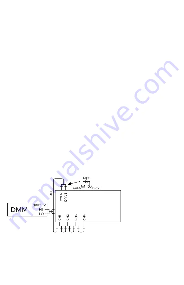
1.11 After communication with the DMM is established, the dialog box will
display connection instructions. Verify that the connections are made in
accordance with the displayed diagram (Figure 1). Select
Next >
to begin
verification.
Figure 1. Connection diagram .
Содержание VR9500
Страница 1: ......
Страница 4: ......
Страница 5: ...1 support vibrationresearch com Hardware Overview Front and Back Panel Inputs Outputs ...
Страница 31: ......
Страница 32: ......


