background image

Chapter 2

Configuring the reflectometry test

Configuring the unit for SmartTEST

8

User Manual

700MAN201 Rev. 002

Configuring the unit for SmartTEST

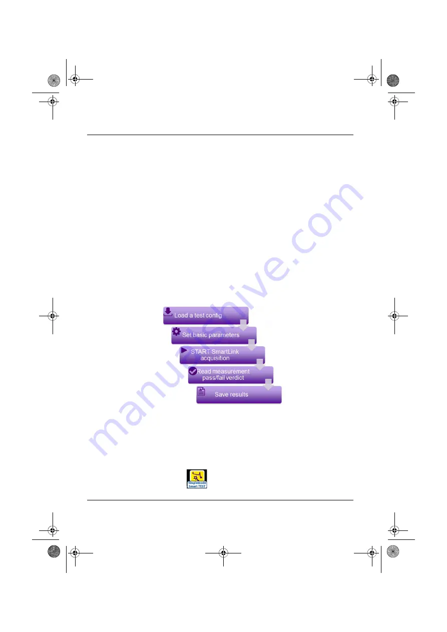
Principle of the SmartTEST

The SmartTEST is used to perform OTDR acquisitions using a pre-loaded configuration 
file (no setup required) and access to essential analysis features.

SmartTEST standard process

1

Select the configuration file, which contains all acquisition parameters and file 
storage setup, and which has been created in Expert mode (see 

“Saving OTDR 

configuration in a file” on page 36

).

2

Configure / modify some parameters before starting the test.

3

Start the acquisition (standard or real time)

4

Save the results

Selecting SmartTEST

The SmartTEST function is available for any OTDR module installed on the equipment.

To select this function, after the equipment starts:

1

Press the 

H

OME


button

2

Select the SmartTEST icon.

The icon turns yellow 

.

Figure 5

Standard SmartTEST Process

OTDR New IHM rev002.book  Page 8  Jeudi, 5. mai 2022  11:50 11

Содержание OTDR 41 A Series

Страница 1: ...OTDR Optical Time Domain Reflectometer For T BERD MTS 2000 4000 V2 5800 SmartOTDR CellAdvisor 5G and OneAdvisor 800 Platforms User Manual OTDR New IHM rev002 book Page i Jeudi 5 mai 2022 11 50 11 ...

Страница 2: ...OTDR New IHM rev002 book Page ii Jeudi 5 mai 2022 11 50 11 ...

Страница 3: ... www viavisolutions com OTDR Functions Optical Time Domain Reflectometer For T BERD MTS 2000 4000 V2 5800 SmartOTDR CellAdvisor 5G and OneAdvisor 800 Platforms User Manual OTDR New IHM rev002 book Page iii Jeudi 5 mai 2022 11 50 11 ...

Страница 4: ...OTDR New IHM rev002 book Page iv Jeudi 5 mai 2022 11 50 11 ...

Страница 5: ...er Trademarks VIAVI MTS T BERD 4000 V2 MTS T BERD 2000 MTS T BERD 5800 SmartOTDR CellAdvisor 5G and OneAdvisor 800 are trademarks or registered trademarks of VIAVI in the United States and or other countries Microsoft Windows Windows CE Windows NT and Microsoft Internet Explorer are either trademarks or registered trademarks of Microsoft Corporation in the United States and or other countries Orde...

Страница 6: ...ttery Directive 2006 66 EC Instructions for returning waste equipment and batteries to JDSU can be found in the WEEE section of VIAVI s Standards and Policies web page If you have questions concerning disposal of your equipment or batteries contact VIAVI s WEEE Program Management team at WEEE EMEA VIAVISolutions com EU REACH Article 33 of EU REACH regulation EC No 1907 2006 requires article suppli...

Страница 7: ... the OTDR Module use 2 Connecting fiber optic cable 2 Inspecting and cleaning connector end faces 2 Optical connector types 3 Connecting Fiber optic cable to test port 4 Optical connectors and interchangeable adapters 5 Interchangeable adapters 5 Cleaning universal connectors 6 Chapter 2 Configuring the reflectometry test 7 Configuring the unit for SmartTEST 8 Principle of the SmartTEST 8 OTDR New...

Страница 8: ...ms parameters 19 Configuring the Display parameters 22 Section Attenuation 22 Section Length 23 Index of refraction 23 Scatter coefficient 24 Distance Unit 25 Results on trace 25 Event Notes 25 Configuring the Advanced parameters 25 Front Connector Meas 26 Detection 26 Configuring the Link Description parameters 27 Fiber Id 28 Fiber Number 28 Change Fiber Nbr 28 Cable Id 29 Direction 29 Location A...

Страница 9: ...cquisition in Real Time mode 40 Principle of the Real time mode 40 Performing acquisition in Real Time 40 Stopping the real time acquisition 42 Performing a measurement with SmartTEST 42 Performing an acquisition with Expert OTDR 43 Multi wavelength acquisition 45 Actions on trace during acquisition 45 Saving results for SmartTEST acquisitions 47 Results display 49 Smart Link view 49 Showing the d...

Страница 10: ...s in overlay 69 Adding traces in overlay 69 Removing a trace 69 Reference Trace function 70 Use of the reference trace function in the Result page 70 Using the reference trace function in the explorer 71 Saving the trace s and generating a report 71 Saving results and creating a report from results page 72 Opening a report 74 Chapter 4 Power meter and Source functions on the OTDR test port 77 Conn...

Страница 11: ...results 87 Loading results 87 Terminated PON Powermeter SmartOTDR 118FA65PPM only 87 Configuring the power meter 87 Configuring the measurement parameters 88 Configuring the alarm parameters 88 Configuring the Link parameters 88 Setting the zero value of the power meter 89 Performing Power Measurement 90 Combo PM OTDR 90 Chapter 5 File management 91 Description of the explorer 92 Opening the file ...

Страница 12: ...dules for T BERD MTS 2000 4000 V2 104 Characteristics of reflectometry measurements 104 Manual Measurement 105 Typical specifications 105 Ranges 109 Class of the lasers of the OTDR modules 112 OTDR modules measurement 112 OTDR Module supply 112 Environment 112 Indoor outdoor 112 Temperature 113 Humidity 113 Pollution degree 113 MPO Switch Module Technical specifications 114 OTDR Technical specific...

Страница 13: ...ersion 118 Chapter 7 Options and accessories 119 Commercial References of measurement modules for T BERD MTS 2000 4000 V2 120 OTDR Modules 120 CWDM OTDR Modules 122 DWDM OTDR Modules 122 MPO Switch Module 122 Options 123 Commercial References of the SmartOTDR 123 Commercial References of optical connectors and adapters 124 Index 127 OTDR New IHM rev002 book Page xiii Jeudi 5 mai 2022 11 50 11 ...

Страница 14: ...Contents xiv User Manual 700MAN201 Rev 002 OTDR New IHM rev002 book Page xiv Jeudi 5 mai 2022 11 50 11 ...

Страница 15: ... the construc tion validation and maintenance of fiber networks The topics discussed in this chapter are as follows Purpose and scope on page xvi Assumptions on page xvi Technical assistance on page xvi Recycling Information on page xvi Conventions on page xvi OTDR New IHM rev002 book Page xv Jeudi 5 mai 2022 11 50 11 ...

Страница 16: ...r the latest TAC information go to http www viavisolutions com en services and support support technical assis tance Recycling Information VIAVI recommends that customers dispose of their instruments and peripherals in an environmentally sound manner Potential methods include reuse of parts or whole prod ucts and recycling of products components and or materials Waste Electrical and electronic Equ...

Страница 17: ...pear in this typeface Type the new hostname Book references appear in this typeface Refer to Newton s Telecom Dictio nary A vertical bar means or only one option can appear in a single command platform a b e Square brackets indicate an optional argu ment login platform name Slanted brackets group required arguments password Table 2 Keyboard and menu conventions Description Example A plus sign indi...

Страница 18: ...ol located on the equipment or its packaging indicates that the equipment must not be disposed of in a land fill site or as municipal waste and should be disposed of according to your national regula tions WARNING Indicates a potentially hazardous situation which if not avoided could result in death or serious injury CAUTION Indicates a potentially hazardous situation which if not avoided may resu...

Страница 19: ...ment The topics discussed in this chapter are as follows Unpacking the device Precautions on page 2 Precautions relating to the OTDR Module use on page 2 Connecting fiber optic cable on page 2 Optical connectors and interchangeable adapters on page 5 OTDR New IHM rev002 book Page 1 Jeudi 5 mai 2022 11 50 11 ...

Страница 20: ...ule use If the equipment is used in a manner not specified by the manufacturer the protection provided by the equipment may be compromised Contact authorized trained and qualified service personnel for all services Fans on OTDR Modules Take care fans may be present on the side of the OTDR product Under normal opera tion no injury may occur to the user Connecting fiber optic cable Inspecting and cl...

Страница 21: ... connectors Optical connector types There are many optical connectors in the market place Always ensure to use a high quality connector that meets the international standards Two main types of connectors are deployed in the telecommunication industry 1 Straight polished connectors so called PC or UPC 2 Angled polished connectors so called APC The PC or UPC type test port is identified by a grey ca...

Страница 22: ...ter ensuring proper cleaning of both end connectors follow the below steps in order to correctly and safely connect the optical fiber into the test port Figure 2 Modules with APC and PC connector Figure 3 PC APC bad connection WARNING VIAVI declines responsibilities of connector damages if a poor quality con nector is used or APC to PC connections made Test port connector repair will be charged OT...

Страница 23: ...to another proceed as follow 1 Unscrew the VIAVI screwdriver to find the 3 different tips for the adapters and set the correct one on the screwdriver 2 Unscrew the current adapter using the VIAVI screwdriver with the correct tip 3 Pull the adapter to remove it NOTE If your connector features a keying mechanism ensure that it is correctly fit ted into the test port s insert NOTE If your connector f...

Страница 24: ...02 4 Set the new adapter and use the VIAVI screwdriver with the correct tip to screw it Cleaning universal connectors Remove the adapter in order to access the ferrule and clean it using a cotton swab Figure 4 Removing and refitting an adapter OTDR New IHM rev002 book Page 6 Jeudi 5 mai 2022 11 50 11 ...

Страница 25: ...e different stages in configuring a reflectometry measurement using an OTDR module in SmartTEST or Expert OTDR The topics discussed in this chapter are as follows Configuring the unit for SmartTEST page 8 Configuring the test in Expert OTDR page 12 OTDR New IHM rev002 book Page 7 Jeudi 5 mai 2022 11 50 11 ...

Страница 26: ...ains all acquisition parameters and file storage setup and which has been created in Expert mode see Saving OTDR configuration in a file on page 36 2 Configure modify some parameters before starting the test 3 Start the acquisition standard or real time 4 Save the results Selecting SmartTEST The SmartTEST function is available for any OTDR module installed on the equipment To select this function ...

Страница 27: ...configuration file to be used for the acquisi tion on Smart Test mode The file is highlighted in purple 3 Press Load to load the selected file and display the current parameters for this configuration NOTE The selection of SmartTEST icon automatically deselects the Expert OTDR icon and vice versa NOTE In case of Singlemode Multimode module there are distinct icons one for multimode with a MM indic...

Страница 28: ...depend on the module type e g DWDM wavelengths available on 4100 DWDM OTDR Modules Distance unit select the unit to be used for distance km kfeet miles meter feet inch Launch cable Define if the Launch Cable must be taken into account for the acquisition No Yes If Yes is selected set the length clicking on text box and enter the distance using the numeric keypad or Click on to perform a measure me...

Страница 29: ... Yes to define alarms and tap in the box to list the available alarms Select the desired one See tables page 21 and page 21 to get the values for each pre defined alarm threhsholds The User thresholds can be modified only in Expert mode and saved in a new configuration file Once all configuration parameters are correctly defined the acquisition can be launched see Performing OTDR acquisitions on p...

Страница 30: ...lable whatever is the OTDR module set onto the equip ment To select this function after the equipment start 1 Press the HOME button 2 Select the Expert OTDR icon The icon turns yellow then the result page displays 3 Press the Setup menu key on the Results page The sub menus allows the selection of NOTE The selection of Expert OTDR icon automatically deselects the SmartTEST icon and vice versa NOTE...

Страница 31: ...atform select to manually the switch port under the parameter Switch Port Acquisition parameters Used for the OTDR acquisition Alarms parameters Display parameters Advanced parameters Link Description parameters Used for the OTDR results saving Project Information parameters File parameters Figure 8 Acquisition parameters If some acquisition parameters are not accessible not visible or displayed i...

Страница 32: ...to but can be modified see Acq Time page 15 Smart Acq not available in Multimode SmartAcq is a fully automated acquisi tion process which uses different pulse widths for a single wave length to maximize the detection The multiple acquisitions are combined to form a single graph and table of events per wavelength combining the most relevant sections of each pulse Range The possible range depends on...

Страница 33: ...ble if Acquisition parameter is set to Manual Auto resolution is selected automatically according to the last two parame ters above High Resolution the highest resolution is applied High Dynamic the lowest resolution is applied to get the highest dynamic range Acq Time Real time the equipment performs up to ten acquisitions per second see Performing acquisition in Real Time on page 40 NOTE Changin...

Страница 34: ...tion continues but a warning displays Yes Abort the OTDR connection is tested and if the state is bad a warning displays and the acquisition stops Launch cable Launch Cable End Receive Cable Start No All the results are displayed and referenced relative to the connector on the module Evt 1 2 3 The results relating to the launch cable are eliminated from the table Attenuation and distances are then...

Страница 35: ...activate the corresponding parameter Include Link End Connector This parameter can be set to Yes if the budget overall loss must include the receive cable start connector loss If those parameters are set to No the budget overall link loss does not include these connectors in the calculation Specific Acquisition parameters with DWDM Modules If a DWDM Module is installed onto the Platform the Setup ...

Страница 36: ...ext10 to display the 10 previous following wavelengths Unit Define the wavelength unit to be used for acquisition THz or nm Dwdm Grid Select one of the pre defined Grid to be used for acquisition 50 GHz 100 GHz 200 Even 200 Odd Or Select User and press the Edit User Dwdm Grid menu key to define a grid Defining a grid 1 Once the menu key Edit User Dwdm Grid is pressed a table displays Figure 10 Acq...

Страница 37: ... the table or to unse lect the selected ones 3 Once configuration of the grid is completed press to return to Setup screen Changes to the table will be saved automatically Configuring the Alarms parameters In the Setup menu press Alarms Once the Alarms menu is displayed configure the thresholds to be applied to the measurement No need to redo an acquisition to apply them to the current measure men...

Страница 38: ...the top right of the screen If Fail is selected select in the Threshold parameter to defined values either manually or according to standards User define your own thresholds values for one or several elements Splice Connector Reflectance Slope Fiber Length Min and Max Total Loss Min and Max ORL TIA 568 3 TIA 568 3 RL35 ISO IEC 11801 2010 or 2014 ISO IEC 14763 3 2019 IEC 61280 4 5 2020 Default Sele...

Страница 39: ... the event is framed in red with a red icon Table 1 Singlemode Modules Splice Loss Connector loss Reflectance Slope ORL Mux Demux Default 0 20 dB 0 50 dB 35 dB 1 00 dB km 27 dB No TIA 568 3 0 30 dB 0 75 dB No 1 00 dB km No TIA 568 3 RL35 0 75 dB 35 dB 1 00 dB km ISO IEC 11801 2010 0 50 dB 35 dB 0 40 dB km ISO IEC14763 3 2014 0 75 dB No 0 40 dB km ISO IEC14763 3 2019 0 75 dB 35 dB 0 40 dB km IEC 61...

Страница 40: ...e table of results in SmartLink view the event is framed in yellow with a yellow icon Configuring the Display parameters In the Setup menu press Display Section Attenuation dB km Displays the section slope in the table of results If the fiber is too short to measure the slope accurately no value is displayed empty field dB Displays the section loss in the table of results With short fiber where th...

Страница 41: ...e extreme distance values are given by the index values 1 30000 to 1 70000 or You can also enter the Link Length if it is known using the Numeric keypad Predefined It is possible to choose one of the predefined values given for certain cables The corresponding indices given in the table below are repeated on the screen Figure 14 Predefined index values Single Mode Wavelength nm 1310 SM 1360 1510 S...

Страница 42: ...ht 1 46750 1 46750 1 46800 1 46850 Fitel Furukawa 1 47000 1 47000 1 47000 1 47000 OFS Lucent Allwave 1 46750 1 46750 1 46750 1 46850 Lucent Truewave 1 47100 1 47100 1 47000 1 47000 SpecTran SM 1 46750 1 46810 1 46810 1 46810 Sterlite 1 46700 1 46700 1 46750 1 46750 Sumitomo Litespec 1 46600 1 46600 1 46700 1 47000 Sumitomo Pure 1 46600 1 46600 1 46700 1 47000 Figure 15 Predefined index values Mult...

Страница 43: ...et miles meter feet inch Results on trace None the trace alone All the trace with results value loss position reflectance and markers Graphics the trace with event markers only Event Notes No no display of notes Notes display notes entered by the user if any Uncertainty display of indicators of the level of confidence in the measurement result Configuring the Advanced parameters In the Setup menu ...

Страница 44: ...ck on the text box and select a value Enter a min level of detection from 0 01 dB Min to 1 99 dB Max No no splice detection Auto to automatically detect splice Reflectance Select if level of detection for reflectance must be defined Click on the text box and select a value Enter a min level of detection from 98 dB Min to 11 dB Max None no reflectance detection All all reflectances are detected cli...

Страница 45: ...tup Each event of the selected wave lengths will then be compared Once parameter is selected click on the text box to display the numeric keypad and select the wished value None Bend will not be detected Auto Bend will be automatically detected Define by user Enter the bend value in dB with direction keys or numeric keypad Mux Demux Once parameter is selected click on the text box to display the n...

Страница 46: ...ng post processing Fiber Id Select the parameter Fiber Id and enter a name for the fiber using the onscreen keyboard Fiber Number 1 Select the parameter Fiber Number and modify the parameter using the left and right direction keys The fiber number can be automatically incremented decremented at each new file save if it has been configured in the File Setup page see Configuring the File parameters ...

Страница 47: ...f the cable using the onscreen keyboard Direction The direction shows if the acquisition has been made from the origin to extremity A B or from the extremity to origin B A Changing direction in the trace simplifies post processing e g for manual bi directional analysis Location A The name of the Location A of the link may be entered here using the onscreen keyboard Location B The name of the Locat...

Страница 48: ... be performed Comment Click on Comment text box to enter a specific comment to the project Configuring the File parameters The File storage parameters must be also configured in order to define how and where the results will be saved in the file system of the equipment 1 In the Setup menu press File Figure 18 Project Information parameters NOTE Refer to the User Manual of the Cable SLM option for ...

Страница 49: ...e text box to display the keyboard and define the directory for files saving In the onscreen keyboard select the pre defined parameters available or press abc key to enter a name manually for the directory Then press Enter to validate Example disk OTDR Test Figure 19 File parameters OTDR New IHM rev002 book Page 31 Jeudi 5 mai 2022 11 50 11 ...

Страница 50: ...the Current Directory for file saving Press to validate Dir This field displays the directory selected created into which the file s will be saved Filenaming Select Filenaming parameter and click on the text box to modify the name of the file for the result trace Figure 20 Directory Onscreen keyboard OTDR New IHM rev002 book Page 32 Jeudi 5 mai 2022 11 50 11 ...

Страница 51: ...me of the file is displayed in grey under Filenaming parameter File Content In this parameter select the file content for traces saving One Trace in case of traces in overlay each trace is saved in a distinct file sor extension All Traces in case of traces in overlay all traces are saved in one single file msor extension One and All Traces this option combines the two previous ones in case of trac...

Страница 52: ... save the results in a sor or msor csor file and to generate a report in a pdf file json file select Yes to save the results in a sor or msor csor file and to generate a json file If all parameters are defined with No only the sor or msor csor file will be saved Report Layout This parameter allows to define the report page setting and is available exclusively if a pdf file has been defined in the ...

Страница 53: ...ed as default settings in factory NOTE This parameter is available only if the report format selected is Pdf ACQUISITION Laser All Acquisition Auto Acq Time Auto OTDR Connector Test Yes Continue Launch Cable No ALARMS Alarm Level None DISPLAY Section Attenuation dB km Section Length Yes Index of Refraction G652 G657 Scatter Coefficient Auto Results on trace Graphics ADVANCED OTDR Connector Meas Ye...

Страница 54: ...quisition in SmartTEST mode is performed in order to be recalled for future acquisition in Expert OTDR To save parameters in a configuration file 1 If necessary press Setup to return to Setup menu 2 Select one parameter in one of the setup page acquisition link 3 Press menu key The onscreen keyboard displays 4 Enter a name for the configuration file max 20 characters FILE Filenaming Auto filenamin...

Страница 55: ... OTDR Loading an existing OTDR configuration To load a configuration file previously created or available in the equipment and apply parameters to new OTDR Expert tests 1 If necessary press Setup to return to Setup menu 2 Press menu key 3 Select the configuration file desired 4 Press Load Load Config You can modify some acquisition or file storage parameters and save them in a new configuration fi...

Страница 56: ...0MAN201 Rev 002 NOTE Most of the configuration files are available into the equipment in disk config Figure 23 Loading a configuration file The main parameters available in the selected configuration file are displayed in the File signature OTDR New IHM rev002 book Page 38 Jeudi 5 mai 2022 11 50 11 ...

Страница 57: ...er describes the different stages in a reflectometry measurement It then describes the functions available on trace s The topics discussed in this chapter are as follows Performing OTDR acquisitions page 40 Saving results for SmartTEST acquisitions page 47 Results display page 49 Advanced functions in Expert OTDR mode page 61 Saving the trace s and generating a report page 71 OTDR New IHM rev002 b...

Страница 58: ... a fiber in process of utilization Performing acquisition in Real Time To carry out an acquisition in real time 1 In OTDR Expert results page press Real Time key or Press Setup key and select Acquisition Acq Time and select Real Time then press Start menu key or In the Setup page of the Smart Test mode press Real Time key see Figure 7 on page 10 The red Testing indicator will go on to show that re...

Страница 59: ...st is automatically detected and reported Table 3 Connection indicator State Connection Good The connection is OK Bad There are several connectors close to the external connector of the equip ment One of the connectors is dirty or badly connected Replace the launch cable make the connection again properly or clean the connector of the OTDR or of the jumper No fiber is connected Figure 24 Example o...

Страница 60: ... at any time Performing a measurement with SmartTEST The acquisition is carried out with the parameters saved in the Configuration file It may be stopped at any time using the START STOP key At the end of test the results page displays 1 From the Setup page press Start Test key to launch measurement see Figure 7 on page 10 The red Testing indicator goes on to show that the equipment is in process ...

Страница 61: ...gings defined as a function of the maximum acquisition time specified in the Acquisition menu and then terminates the acquisition The acquisition is carried out with the parameters previously selected in the Setup Acquisition menu It may be stopped at any time using the STOP key 1 Press the START key to start the acquisition Figure 25 Acquisition in progress in SmartTEST Elapsed acquisition time T...

Страница 62: ...nd remaining acquisition time At the end of the acquisition a beep is emitted the trace is displayed and an automatic measurement is started Figure 26 Acquisition in progress with Expert OTDR Elapsed acquisition time Total acquisition time NOTE During acquisition the traffic on fiber is automatically detected see Traffic detection page 41 NOTE To stop the acquisition the STOP key may be pressed at...

Страница 63: ... available on results in progress Actions on Display Positioning Cursors A and B Click on the Cursor line on the trace to select the cursor and click on the trace Set both cursors A B to control distance between two points Set one cursor A or B to get the distance from one point Set one cursor A or B to zoom on this cursor Zooming on trace Click on the key or to zoom in or out on the trace Click o...

Страница 64: ...ameters in Real Time mode only You can modify the acquisition parameters during the acquisition 1 Press the Setup key 2 Scroll through the possible values of the parameters Performing measurements during acquisition Real Time mode only The real time mode allows to make Loss ORL or Reflectance measurement using the A B cursors and the key Average 1 Position A B cursors on the trace 2 Click on Measu...

Страница 65: ...7 Saving results for SmartTEST acquisitions Once the acquisition is completed the results trace displays in Smart Link view with the Save key displayed 1 Click on Save key to save the results in a file The Recording Information page displays Figure 28 Example of loss measurement OTDR New IHM rev002 book Page 47 Jeudi 5 mai 2022 11 50 11 ...

Страница 66: ...iption Cable Id click on the cable name currently defined to display the edition keyboard and enter a new cable name Fiber Id click on the fiber name currently defined to display the edition keyboard and enter a new fiber name Fiber Number click on the fiber number currently defined to display the numeric keyboard and enter a new fiber number Location A Location B click on the location name curren...

Страница 67: ...re displayed on the Results page According to the mode of acquisition Expert OTDR or SmartTEST the results page offers similar functions but also different functions Smart Link view Once the results trace is displayed click on Smart Link key to display the Smart Link view At the end of the acquisition a pop up window displays the overall test resuls Tap this window to close it NOTE The file is sav...

Страница 68: ...is divided into three zones Zone1 the Event line which is a graphical representation of the fiber with the detected events position on this fiber and the alarm status icon or the Info bar with the acquisition parameters of the trace together with a small scale represen tation of the trace Figure 30 SmartLink function Zone 2 Zone 3 Zone 1 OTDR New IHM rev002 book Page 50 Jeudi 5 mai 2022 11 50 11 ...

Страница 69: ...o Alarm thresholds defined in the setup screen Showing the detailed information of one event The information concerning the event its type and the alarm thresholds defined for this event can be displayed from the SmartLink screen 1 Select the event for which information must be displayed on the graphic The event is highlighted in purple once selected A frame displays and describes the event type t...

Страница 70: ...gure 32 Event Details NOTE The event is displayed with a red icon if it is above the alarm thresholds defined in the setup menu A green icon is displayed if it lies within the thresholds A yellow icon is displayed if the value is above a Warning threshold No icon is displayed if no alarm has been defined in the Setup menu OTDR New IHM rev002 book Page 52 Jeudi 5 mai 2022 11 50 11 ...

Страница 71: ...and displaying results Results display User Manual 700MAN201 Rev 002 53 Click on Assistant softkey to return to Setup Information page Figure 33 Example of results trace with SmartTEST OTDR New IHM rev002 book Page 53 Jeudi 5 mai 2022 11 50 11 ...

Страница 72: ...ectometry trace is displayed with a dotted vertical line set on the start of launch cable if the Launch Cable End parameter is defined in the SETUP menu Figure 34 Example of results trace with Expert OTDR Table 4 Alarms display Fail Indicates that at least one result exceeds the alarm thresholds defined in the configuration file used for acquisition Results are displayed in red in table Valid Indi...

Страница 73: ...SETUP menu see Configuring the test in Expert OTDR page 12 Attenuation and reflectance results for an event will be displayed if they can be calculated The reflectance of an event is always measured except when the event causes a satu rated Fresnel peak or if it is drowned out by noise In this case the equipment displays to show that the actual reflectance exceeds the value displayed Results table...

Страница 74: ... corresponding marker Non reflective attenuation e g splice Splitter Mux Demux Reflective event e g connector Ghost reflection Slope of the fiber when no fault follows the slope End of fiber OTDR connector Bend Bend on OTDR Connector The event underlined in purple is the one the nearest of the cursor set on trace To visu alize an event click on this event on the table to set the cursor on it onto ...

Страница 75: ...rsor must be set Above the trace is shown the 2 points loss measurement between the two cursors together with the distance between the two cursors Click on the Lock icon in order to select both cursors and move it at the same time on the trace keeping the current space between them Section Expert OTDR only The length of the section the distance between the marker of the event and the previous mark...

Страница 76: ...izontally or verti cally position your finger on a cursor and move it on trace maintaining your finger pressed and moving it toward left or right once a zoom is performed double click on the zoomed zone to undo the zoom Zooming on the different events in succession 1 Set the cursor on one event 2 Define a zoom on this event 3 Click on another event in the results table The cursor is automatically ...

Страница 77: ... Table to display exclusively the measurement results in a table The list of all the events detected during acquisition or manually measured are displayed in a table The events exceeding alarm thresholds are displayed in red whereas those lying withing the thresholds are displayed in green Select Failed on the button to display exclusively the results exceeding the thresholds Figure 36 Table View ...

Страница 78: ...icon to be modified in the results table 2 In SmartLink view in the menu open select the new type of event to be applied In Trace view click first on Event Codes and select the new type of event to be applied Click on the cross to cancel the modification Figure 37 Event Code Click to validate Click to cancel Click to validate Click to cancel NOTE The event modification is automatically applied on ...

Страница 79: ...vents and proceeds to the measurements 2 Addition of events see Addition of events on page 61 in the cases of splices showing low attenuation and of close events The equipment then automatically measures the slope before and after the markers selected and measures the attenuation of the splice 3 Addition of manual measurements if necessary for deeper analysis The equip ment performs the measuremen...

Страница 80: ...d out on the second marker to obtain results for this marker a manual measurement is necessary If you press the key when the cursor is very close to a marker the latter will be deleted Deleting events To delete an event move the cursor onto the event and press the key The event selected will be deleted and a complete measurement without this event is carried out Deletion of events can cause incorr...

Страница 81: ...ess Calculate key The slope of the specified trace section is displayed The result is displayed on the screen between the two slope indicators and The measurement results are also available in the table Click again on Anaysis to return to results table display Distance shows the distance between the beginning of the trace and the end of the slope If no result is displayed in the table this means t...

Страница 82: ...ORL It is possible to carry out an ORL measurement on a part of the fiber Follow the following procedure to measure a part of the fiber 1 Position the cursors A and B to delimit the section that you wish to measure 2 Press the Analysis then select ORL from the manual measurement bar 3 Press Calculate key The ORL is measured for the section of trace defined ORL on a saturated trace If saturation oc...

Страница 83: ...peak to calculate automatically the maximum reflectance 3 Press the Analysis then click on Reflect 4 Press Calculate key The Reflectance value is defined in dB and displayed in the trace in purple Splice measurements There are two methods of carrying out manual measurements of splices on the trace the two cursor method and the five cursor method The five cursor method is the more accurate as it ta...

Страница 84: ...e splice marker is placed at the point defined by the first left hand cursor and the result is displayed on the screen If the fault is reflective the reflectance value is also measured and displayed These results are added to the table of results Five points method To carry out a splice measurement by the five points method 1 Measure the slope preceding the fault to be measured then the slope foll...

Страница 85: ... an event is added with the key after manual measurements have been per formed then all the events on the trace will be converted into AUTO markers and an automatic measurement will be performed using these events The previous manual measurements will be lost Provided the event lock the automatic measurement following the acquisition is carried out using the events which were present before the ac...

Страница 86: ...splayed on the screen at once either to compare traces acquired on a number of different fibers in the same cable or to observe changes over time in traces taken of one and the same fiber Overlaying several traces stored in memory To display up to 18 traces from the memory deleting the current trace s already loaded 1 Press the File softkey 2 Select the files of the traces for display 3 Press the ...

Страница 87: ...overlay it must first be selected clicking on its corresponding number Adding traces in overlay With one or more traces already displayed to add further traces to the display the number of traces displayed cannot exceed 8 1 Define at least one trace as reference see Reference Trace function on page 70 2 Press File and in the Explorer select the files of the traces to be added 3 Press Load key 4 Pr...

Страница 88: ...d in purple and underlined 2 Long click on this trace number A new menu displays 3 Click on Set curve As Reference The active trace becomes the reference trace the trace number is displayed with square brackets and with a REF indicator To define all the traces displayed as reference traces click on Set All As Reference key whatever is the active trace Removing the reference trace s To change one r...

Страница 89: ...r A trace stored in memory can be set as reference trace before loading one or several standard trace s To open one or several reference trace s 1 Go on the File Explorer clicking on File key from the results page 2 Select the trace s to be defined as reference 3 Click on Load and select Reference Yes on the key 4 Click on View Trace s or Load Trace Config The REF mark appears on the trace number ...

Страница 90: ... pdf json Saving results and creating a report from results page To save the trace and generate a report 1 Press Fast Report menu key A menu displays next to the fast report key 2 In the menu configure the file saving mode and the report a If wished define modify the name for the Cable clicking on Cable Id and on the text box to display the edition keyboard b Modify the Fiber Number c In the Locat...

Страница 91: ... In the edition keyboard click on key to apply the auto filenaming see Filenaming page 32 h In the Save Mode parameter select txt file select Yes to save the results in a sor file and to generate a txt file of the results pdf file select Yes to save the results in a sor file and to generate a report in a pdf file json file select Yes to save the results in a sor file and to generate a json file If...

Страница 92: ...rlay 3 sor files and 3 pdf txt files will be saved If in the File Setup page Setup File the parameter File Content is defined with All Traces one single msor file and one single txt pdf report will be gener ated bringing together all traces Example if 3 traces are displayed in overlay one single msor file and one single txt pdf file with one trace per page except if the results table is too long f...

Страница 93: ...DF report CAUTION To modify the VIAVI logo set by default on the header of the pdf report save your logo in a jpg file called logo jpg and place it to the root of the disk disk logo jpg NOTE A PDF Report can also be generated from the File Explorer page see Gen erating pdf report s on page 99 OTDR New IHM rev002 book Page 75 Jeudi 5 mai 2022 11 50 11 ...

Страница 94: ...Chapter 3 Launching a reflectometry test and displaying results Saving the trace s and generating a report 76 User Manual 700MAN201 Rev 002 OTDR New IHM rev002 book Page 76 Jeudi 5 mai 2022 11 50 11 ...

Страница 95: ...rtOTDR 118FA65PPM APC comes by default with a dual band power meter The topics discussed in this chapter are as follows Connecting to the test port on page 78 Configuring the Power meter on page 78 Activating the Source function on page 80 LTS Results page on page 80 Performing a power level measurement on page 83 Performing an insertion loss measurement on page 84 Storing and reloading results on...

Страница 96: ...ilable for source and power meter typically 1310 1490 1550 1625 1650 nm In case of Live Filtered port used for in service measurement at 1625 1650 nm there is no power meter function on the port except for SmartOTDR 118FA65PPM APC Configuring the Power meter To activate the function 1 Press the HOME button Figure 44 Optical Powermeter and Source function share the same port as the OTDR Connector I...

Страница 97: ... desired wavelength also directly available on the main result page Auto Identify automatically the wavelength when used with VIAVI optical light sources 1310 1490 1550 1625 or 1650 nm measurement performed at specified wavelength Beep on modulation Set it to Yes if a sound must be emitted when a modulation occurs Unit Power level measurement unit Watt dBm for absolute power level measurement dB f...

Страница 98: ...ng the alarm parameters Alarms Activation of pass fail analysis any result below the lower threshold or above the upper threshold will be displayed in red on the Results page Min and max thresholds Choice of lower and upper thresholds for each available wavelength from 60 to 40 dBm Activating the Source function To activate the function 1 Press the HOME button 2 Select the light source icon in OTD...

Страница 99: ...ilable frequency 270Hz 330Hz 1KHz or 2KHz VIAVI Auto the wavelength of the measured signal the reference level expressed in dB the level of Attenuation Compensation Table of results For one and the same fiber the power meter displays a table of all the different tested wavelengths The table shows the power level measured in dBm the relative power in dB and the reference level in dBm if units dB to...

Страница 100: ...s of a link This refer ence value is dis played under the measurement result until a new reference is performed Keep the power level value displayed in the table below Deletes all the results values displayed in the table Combo PM OTDR If the ExpertOTDR function is active at the same time as the power meter the Combo PM OTDR function becomes available in the control bar It allows to combine in the...

Страница 101: ...0 Hz 1 kHz 2 kHz Auto the light source is modulated at proprietary frequencies to enable VIAVI power meters to automatically detect the wavelength TwinTest the light source is modulated and cycling through the available wavelengths This mode is compatible with VIAVI power meters to measure multiple wavelengths automatically and sequentially CW continuous waveform with a constant amplitude and freq...

Страница 102: ...d out to get a reliable and accurate loss measurement Setting the zero value of the power meter 1 Close the protective cap of the OTDR port so no light can be seen by the power meter photodetector 2 In the Setup menu press Zero 3 Wait until the dialog box Offset nulling completed is displayed 4 Hit any key to continue Performing a reference Using two equipments with an OTDR module including a lase...

Страница 103: ...yellow to show it is active c In the Results page press Standard Ref for each wavelength The actual power level is set as the new reference level for the selected wavelength Then the displayed value is around 00 00 dB The reference levels are stored and entered in the setup fields Measurement on the fiber under test Once the references have been performed on both units After a Side by side referen...

Страница 104: ...nditioner 2 Connect the Powermeter port 2 to the jumper 3 Connect extremities of the mode conditioner and jumper to the fiber under test using the appropriate method ex keying mechanism for FC PC types 4 On equipment 1 select Laser START to activate the light source Storing and reloading results Report Setup Press on Setup softkey then Report File s save in set the directory where the file s will ...

Страница 105: ...uivalent to a csv and can be opened with a spreadsheet program on a computer where all measurement results can be easily retrieved and the table format customized Loading results In order to load previous power level measurements go to the file Explorer select a file with the extension Lts and press Load View trace s Terminated PON Powermeter SmartOTDR 118FA65PPM only SmartOTDR 118FA65PPM comes wi...

Страница 106: ...the different avail able pair of wavelengths Or press Setup then Measurement and select the relevant pair of wavelengths Configuring the alarm parameters Alarms Activation of the pass fail analysis any result below the lower threshold or above the upper threshold will be displayed in red on the Results page Min and max thresholds Choice of lower and upper thresholds for each available wavelength C...

Страница 107: ...r is automatically decremented at each new file save User defined Use Edit Number softkey to enter the increment decrement value for fiber number Note to decrement the number enter the sign before the number Example 1 Min 999 Max 999 Auto 0 No the Fiber number will not be modified Technician Id To enter a Tech ID using the alphanumeric keyboard Setting the zero value of the power meter 1 Close the...

Страница 108: ...efined in the setup menu and in red if it exceeds the thresholds The results are displayed in blue if no alarm is defined 2 Press Keep results to keep the current results in the table The values are then displayed in the table but not saved yet 3 Press Save and enter a file name with the alphanumeric keyboard Combo PM OTDR If the ExpertOTDR mode is activated at the same time as the PON Power meter...

Страница 109: ...hapter 5 File management The topics discussed in this chapter are as follows Description of the explorer on page 92 Saving and loading files on page 95 Exporting files on page 97 OTDR New IHM rev002 book Page 91 Jeudi 5 mai 2022 11 50 11 ...

Страница 110: ...rename directories and files The left hand part presents the storage architecture Click on the left of the screen to move around among all the media and their respective directories The right hand part displays all the files present in the directory selected At the top of the screen the file signature selected is repeated see Figure 54 on page 93 Figure 53 Example of explorer Free space available ...

Страница 111: ...BERD Buttons on the right of the screen Saving traces Three buttons are used to save one or more traces Click on Store menu key and then select Save allows to save the current trace opened Save All allows to store all the traces displayed in overlay OTDR in one single file The softkey Next Trace is used to activate the menu of the following trace when several OTDR traces are in overlay Storage med...

Страница 112: ...sted or deleted 2 Click on Edit menu key 3 Select the action to be performed 4 For directory or file paste select a new directory and click to paste the element For renaming directory or file once the Rename Directory File menu key is pressed enter the new name in the Edition keyboard and click to validate For Directory File deletion once the Delete menu key is pressed confirm the deletion clickin...

Страница 113: ...e all the traces opened whereas the Save menu key allows to save exclusively the trace described in the file signature This will open automatically the edition keyboard in order to give a filename for the active trace Loading files and displaying traces To access the functions for loading one or more files select the file s in the explorer and press Load Figure 56 Saving active trace from the expl...

Страница 114: ... with a different module from the current one when the trace was acquired certain configuration parameters cannot be updated A message warns the user of this If several traces are selected the configuration used will be that of the first trace If the number of traces added and the number of traces present is greater than 8 then the last traces added will not all be taken into account Loading sever...

Страница 115: ...the active application the function must be activated in Test page or at least one result trace must be opened to get the tab and display files in the Link Manager page For example if the Link Mgr function is selected in the tab OTDR only the link informa tion from the OTDR files will be displayed whether in multimode or singlemode Select Link Mgr with the menu key Explorer Link Mgr to display the...

Страница 116: ... directory in a txt file 1 Select the Link Manager function 2 Select the directory to open 3 Select one file from the list 4 Click on Export menu key The txt file is automatically generated in the same directory as the one selected for the export The name by default for the txt file is fiber_info_otdr txt NOTE The files in the Link Manager window can be sorted according each column available for a...

Страница 117: ...he active tab Once generated the txt file can be transferred onto a PC and opened via a spreadsheet program e g Excel Generating pdf report s Several files of a same type example all OTDR files can be generated in one several pdf report s 1 Select the file s to be generated in a pdf report 2 Press Export Report menu keys NOTE The txt file can be renamed once it is saved Figure 58 Example of a dire...

Страница 118: ...enter the name for the report 6 Press to validate and launch the report Once report is generated a beep is emitted Figure 59 Report 1 Trace and Multi with OTDR files PDF Report 1 Trace mode PDF Report Multi mode CAUTION To modify the VIAVI logo set by default on the header of the pdf report save your logo in a jpg file called logo jpg and place it to the root of the disk disk logo jpg NOTE The rep...

Страница 119: ...lorer select the txt pdf files generated with the trace files you want 2 Click on Export Merge key A beep is emitted once process is completed The file is saved with the filename merged_yyyy_mm_day__hr_mn_sec pdf txt It is automatically saved in the same directory as the one where the txt pdf files have been selected The merging can be done exclusively from files of the same format Pdf and txt fil...

Страница 120: ...Chapter 5 File management Exporting files 102 User Manual 700MAN201 Rev 002 OTDR New IHM rev002 book Page 102 Jeudi 5 mai 2022 11 50 11 ...

Страница 121: ... or SmartOTDR and the OTDR technical speci fications for SmartOTDR The topics discussed in this chapter are as follows OTDR modules for T BERD MTS 2000 4000 V2 on page 104 Environment on page 112 OTDR Technical specifications for SmartOTDR on page 114 NOTE For specifications regarding the environment refer to the Base Unit user manual OTDR New IHM rev002 book Page 103 Jeudi 5 mai 2022 11 50 11 ...

Страница 122: ...istance for LA MM and QUAD excluding errors of calibration of refractive index of the fiber 0 5m sampling resolution 10 5 x distance for MA2 MA3 B and C Modules excluding errors of calibration of refractive index of the fiber Display span 3 25 m up to 400 km according to the Module Attenuation measurement Dual cursor Resolution of display 0 001 dB Resolution of cursor 0 001 dB Linearity 0 05 dB dB...

Страница 123: ...asurement of splice by 2 or 5 points method Typical specifications Typical values measured at 25 C for all modules unless specified Multimode Module Multimode OTDR Module 41XXMM Central Wavelength1 1 Laser in CW mode at 25 C 850 1300 nm 30 nm Typical RMS Dynamic Range2 2 Typical value corresponding to the difference in dB between the level of back diffusion extrapolated at the beginning of the fib...

Страница 124: ...0 km Pulse width 5ns to 20 µs Event Dead Zone 4 4 EDZ measured at 1 5 dB below the peak of a non saturated reflecting event at shortest pulse width 1 5 m 0 7 m 1383 nm 1 76 m5 5 EDZ measured at 1 5 dB below the peak of a non saturated reflecting event at 10 ns 0 7 m Attenuation Dead Zone 6 6 ADZ measured at 0 5 dB on the basis of a linear regression from a reflectance of type FC UPC 55 dB at short...

Страница 125: ... ratio non reflective splitter at 1310nm using 200ns pulsewidth 7 Measured on a 16 dB loss typical 1x32 split ratio non reflective splitter at 1310nm using 100ns pulsewidth Singlemode Modules 41xxA 41xxB 41xxC Multimode Singlemode OTDR Module Central Wavelength 1 850 1300 nm 30 nm 1310 1550 nm 20 nm Typical RMS Dynamic Range 2 26 24 dB 37 35 dB Distance Range Up to 80 km Up to 260 km Pulse width 3...

Страница 126: ... source in continuous mode 3 5 dBm Modes5 CW 270Hz 330Hz 1kHz 2kHz 1 Guaranteed with laser at 25 C measured at 10 µs 2 Value corresponding to the difference in dB between the backscattered level extrapolated at the origin of the fiber and the RMS noise level after 3 minutes of averaging with the largest pulsewidth 3 EDZ measured at 1 5 dB below the peak of a non saturated reflecting event at short...

Страница 127: ...level after 3 minutes of averaging with the largest pulsewidth 2 EDZ measured at 1 5 dB below the peak of a non saturated reflecting event at shortest pulsewidth 3 ADZ measured at 0 5 dB on the basis of a linear regression from a reflectance of type FC PC 55 dB at shortest pulsewidth 4 Remove 3 dB if used in modulation mode 270 330 1k 2kHz Auto DWDM Modules 41DWDMC 5 ns 30 ns 60ns 100 ns 300 ns 1 ...

Страница 128: ...x x x 2 km x x x x x x 5 km x x x x x x x 10km x x x x x x x 20km x x x x x x x x 40km x x x x x x x x x x 80 km x x x x x x x x 160km x x x x x x 260km x x x x 5ns 10ns 30ns 100ns 200ns 500ns 1us 3us 10us 20us 100 m x x x 500 m x x x 1 km x x x x 2 km x x x x x x 5 km x x x x x x x 10 km x x x x x x x 20 km x x x x x x x x 40 km x x x x x x x x x x 80 km x x x x x x x x 160 km x x x x x x 260 km ...

Страница 129: ... km x x x x x 10 km x x x x x x 20 km x x x x x 40 km x x x 80 km x x x 10 ns 30 ns 100 ns 300 ns 1 µs 3 µs 10 µs 20 µs 0 5 km x x 1 km x x 2 km x x x 5 km x x x x 10 km x x x x x 20 km x x x x x x 40 km x x x x x x x x 80 km x x x x x x x 160 km x x x x x 260 km x x x 10 ns 30 ns 100 ns 300 ns 1 µs 3 µs 10 µs 20 µs 0 5 km x x 1 km x x x 2 km x x x x 5 km x x x x x 10 km x x x x x 20 km x x x x x ...

Страница 130: ...um power consumption is 8 W Environment Indoor outdoor Backlight high visibility color screen High visibility capacitive touchscreen for indoor and outdoor use 40 km x x x x x x x x 80 km x x x x x x x 160 km x x x x x x 260 km x x x 10 ns 30 ns 100 ns 300 ns 1 µs 3 µs 10 µs 20 µs Module Standard IEC 60825 1 2014 FDA21CFR 1040 10 Singlemode LA MA2 A B and C OTDR Modules Class1 Class 1 Singlemode M...

Страница 131: ...ials Waste Electrical and electronic Equipment WEEE Directive In the European Union this label indicates that this product should not be disposed of with household waste Il should be deposited at an appropriate facility to enable recovery and recycling CAUTION It is strongly recommended to work on the Platform in its glove when the product is used outdoors in rainy weather CAUTION AC DC power supp...

Страница 132: ...d 1625 nm 2 2 5 dB maximum 1 2 dB typ Input port SC APC Output port MPO APC pinned Laser safety class 21 CFR Class 1 Distance units Kilometer meter feet and miles Group index range 1 300000 to 1 700000 in 0 00001 steps Number of data points Up to 256 000 data points Distance measurement Automatic or dual cursor Display range 0 1 km to 260 km for single mode Cursor resolution 1 cm Sampling resoluti...

Страница 133: ...racteristics of reflectometry measurements Distance measurement Automatic or Dual cursor Distance displayed takes into account the calibration of the refractive index of the fiber Index adjustable from 1 30000 to 1 70000 in steps of 0 00001 Resolution of display 1 cm max Resolution of cursor 1 cm max Dangerous voltage 70VDC is present inside of the product Do not attempt to remove cover when produ...

Страница 134: ...cy 2 dB Automatic measurement Automatic measurement of all the elements of the signal Slope measurement by least squares or 2 points of measurement Display threshold of faults 0 to 5 99 dB in steps of 0 01 dB for event thresholds 11 to 99 dB in steps of 1 dB for the reflectance 0 01 to 5 99 dB in steps of 0 01 dB for attenuation Display of slope and attenuation for a segment of fiber Display of th...

Страница 135: ... 90 m 1 35 m Attenuation Dead Zone4 2 5 m 4 m Splitter Attenuation Dead Zone 45 m after 15dB splitter loss5 40 m after 12dB splitter loss6 1 Laser at 25 C and measured at 10 µs 2 Typical value corresponding to the one way difference in dB between the extrapolated backscatter ing level at the beginning of the fiber and the RMS SNR 1 noise level after 3 minutes averaging and high dynamic resolution ...

Страница 136: ...1490 1550 1625 1650 nm Accuracy at calibrated wavelengths 0 5 dB at 30 dBm 3 Input power range 60 dBm to 10 dBm Maximum resolution 0 01 dB 0 01nW Measurement range 0 to 55 dBm Linearity 0 5 dB4 PON XG PON Power Meter E118FA65PPM version Wavelengths 1490 1550 nm 1490 1578 nm Measurement ranges 1490 nm 35 to 5 dBm 1550 1578 nm 35 to 23 dBm Measurement accuracy 0 5 dB Channels isolation from external...

Страница 137: ...or T BERD MTS 4000 V2 and the references for the SmartOTDR The topics discussed in this chapter are as follows Commercial References of measurement modules for T BERD MTS 2000 4000 V2 on page 120 Commercial References of the SmartOTDR on page 123 Commercial References of optical connectors and adapters on page 124 OTDR New IHM rev002 book Page 119 Jeudi 5 mai 2022 11 50 11 ...

Страница 138: ...e 850 1300 nm OTDR Module E4123MM LA Modules Commercial References LA OTDR 1310 1550 nm Module with source option E4126LA LA OTDR 1550 nm Module with source option E4115LA LA OTDR filtered 1650 nm Module E4118RLA65 MA2 Modules Commercial References Metro Access 1310 1550 nm OTDR Module with APC connector and continuous light source E4126MA2 APC Metro Access 1310 1550 nm OTDR Module with PC connect...

Страница 139: ...5 nm OTDR Module with APC connector and continuous light source E4136MA3 APC Metro Access PON 1310 1550 1625 nm OTDR Module with PC connector and continuous light source E4136MA3 PC Metro Access PON 1310 1550 nm and Filtered 1650 nm OTDR Module with APC connector and continuous light source E4138FMA365 APC B Modules Commercial References Module B OTDR 1310 1550 nm PC APC E4126B PC APC Module B OTD...

Страница 140: ...471nm to 1611nm for T BERD MTS2000 and 4000 V2 E41CWDM8U CWDM OTDR Module from 1431nm to 1611nm for T BERD MTS2000 and 4000 V2 E41CWDM10U CWDM OTDR Module from 1271nm to 1451nm for T BERD MTS2000 and 4000 V2 E41CWDM10L 2 Specify optical connector of each OTDR ports Modules Commercial References Tunable DWDM APC OTDR Module C Band with Tunable Light Source included E41DWDMC APC Tunable DWDM PC OTDR...

Страница 141: ... Configurations1 Commercial References SmartOTDR 1550nm A Range Handheld Tester With Continuous Light Source PC Connector E100A PC SmartOTDR 1550nm A Range Handheld Tester with Continuous Light Source APC Connector E100A APC SmartOTDR filtered 1650 nm A Range Handheld Tester with APC connector E118FA65 APC SmartOTDR filtered 1650 nm A Range Handheld Tester with PON XGPON 1490 1550 1578 nm Power me...

Страница 142: ...mercial References Front Panel Optical Connectors for modules1 Single mode Universal OTDR Except LA OTDR Modules 1 A connector universal must be specified at time of order of the module Commercial References Universal PC Connector with FC adapter EUNIPCFC Universal PC Connector with SC adapter EUNIPCSC Universal PC Connector with ST adapter EUNIPCST Universal PC Connector with DIN adapter EUNIPCDI...

Страница 143: ...rences Universal PC Connector with FC adapter EUNIPCFCMM Universal PC Connector with SC adapter EUNIPCSCMM Universal PC Connector with ST adapter EUNIPCSTMM Universal PC Connector with DIN adapter EUNIPCDINMM Universal PC Connector with LC adapter EUNIPCLCMM Additional Adapters for Universal Connectors1 1 Interchangeable in the field Commercial References Universal FC Adapter EUFCAD Universal FC A...

Страница 144: ...Chapter 7 Options and accessories Commercial References of optical connectors and adapters 126 User Manual 700MAN201 Rev 002 OTDR New IHM rev002 book Page 126 Jeudi 5 mai 2022 11 50 11 ...

Страница 145: ...104 115 D Distance Specif OTDR measurement 104 115 E Environment 103 Event memorization 67 Event OTDR 54 55 61 Icons 56 F Fans 2 Fiber end 27 File expedition 93 Loading 95 Save 95 Signature 93 File setup menu 92 G Ghost 31 56 I Index Of Refraction IOR 23 IOR Specifications 104 115 L Laser 14 Laser classes 112 M Mail OTDR New IHM rev002 book Page 127 Jeudi 5 mai 2022 11 50 11 ...

Страница 146: ...s references 123 Results parameters 30 Specif measurement 104 115 OTDR Events Delete 62 Hints 62 Representation 61 OTDR module Size 112 OTDR ranges 109 Overlay traces Add 69 Display 69 Remove 69 P Power meter Alarms 80 88 Attenuator 80 Configuration 78 Connection 78 Measurement process 83 specifications 118 Zero value 84 89 Pulse 14 R Range 14 Reference trace 70 References 119 Reflectance 56 Speci...

Страница 147: ...OTDR New IHM rev002 book Page 129 Jeudi 5 mai 2022 11 50 11 ...

Страница 148: ...2 55 5543 6644 EMEA 49 7121 862273 APAC 1 512 201 6534 All Other Regions viavisolutions com contacts email TAC viavisolutions com address 6001 America Center Drive San Jose CA 95002 USA 700MAN201 Rev 002 05 22 English OTDR New IHM rev002 book Page 130 Jeudi 5 mai 2022 11 50 11 ...

Отзывы: