


7
Plasma TV Service Manual
05/01/2006
•
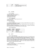
Multistandard true synchronous demodulation with active carrier regeneration (very linear demodulation,
good intermodulation figures, reduced harmonics, excellent pulse response)
•
Gated phase detector for L/L accent standard
•
Fully integrated VIF Voltage Controlled Oscillator (VCO), alignment-free; frequencies switchable for all
negative and positive modulated standards via I
2
C-bus
•
Digital acquisition help, VIF frequencies of 33.4, 33.9, 38.0, 38.9, 45.75 and 58.75 MHz
•
4 MHz reference frequency input [signal from Phase-Locked Loop (PLL) tuning system] or operating as
crystal oscillator
•
VIF Automatic Gain Control (AGC) detector for gain control, operating as peak sync detector for negative
modulated signals and as a peak white detector for positive modulated signals
•
Precise fully digital Automatic Frequency Control (AFC) detector with 4-bit digital-to-analogue converter;
AFC bits via I
2
C -bus readable
•
TakeOver Point (TOP) adjustable via I
2
C-bus or alternatively with potentiometer
•
Fully integrated sound carrier trap for 4.5, 5.5, 6.0 and 6.5 MHz, controlled by FM-PLL oscillator
•
Sound IF (SIF) input for single reference Quasi Split Sound (QSS) mode (PLL controlled)
•
SIF AGC for gain controlled SIF amplifier; single reference QSS mixer able to operate in high performance
single reference QSS mode and in intercarrier mode, switchable via I
2
C-bus
•
AM demodulator without extra reference circuit
•
Alignment-free selective FM-PLL demodulator with high linearity and low noise
•
I
2
C-bus control for all functions
•
I
2
C-bus transceiver with pin programmable Module Address (MAD).
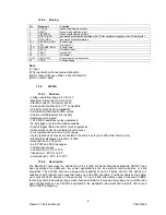
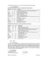
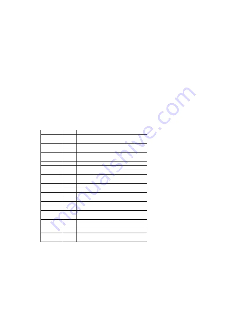
12.3.3. Pinning
SYMBOL PIN DESCRIPTION
VIF1 1
VIF differential input 1
VIF2
2
VIF differential input 2
OP1
3
output 1 (open-collector)
FMPLL
4
FM-PLL for loop filter
DEEM
5
de-emphasis output for capacitor
AFD
6
AF decoupling input for capacitor
DGND
7
digital ground
AUD
8
audio output
TOP
9
tuner AGC TakeOver Point (TOP)
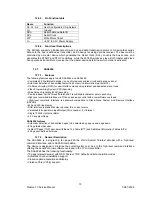
SDA
10
I
2
C-bus data input/output
SCL
11
I
2
C-bus clock input
SIOMA
12
sound intercarrier output and MAD select
n.c.
13
not connected
TAGC
14
tuner AGC output
REF
15
4 MHz crystal or reference input
VAGC
16
VIF-AGC for capacitor; note 1
CVBS
17
video output
AGND
18
analog ground
VPLL
19
VIF-PLL for loop filter
V
P
20
supply voltage (+5 V)
AFC
21
AFC output
OP2
22
output 2 (open-collector)
SIF1
23
SIF differential input 1
SIF2
24
SIF differential input 2
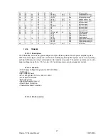
12.4. TEA6415C
12.4.1. General
Description
The main function of the IC is to switch 8 video input sources on 6 outputs. Each output can be
switched on only one of each input. On each input an alignment of the lowest level of the signal is made
(bottom of synch. top for CVBS or black level for RGB signals). Each nominal gain between any input
and output is 6.5dB. For D2MAC or Chroma signal the alignment is switched off by forcing, with an
external resistor bridge, 5 V
DC
on the input. Each input can be used as a normal input or as a MAC or
Содержание 17MB11
Страница 1: ...50 PLASMA TV 17MB11 SERVICE MANUAL...
Страница 50: ...47 Plasma TV Service Manual 25 08 2005 15 CIRCUIT DIAGRAMS...
Страница 51: ...48 Plasma TV Service Manual 25 08 2005...
Страница 52: ...49 Plasma TV Service Manual 25 08 2005...
Страница 53: ...50 Plasma TV Service Manual 25 08 2005...
Страница 54: ...51 Plasma TV Service Manual 25 08 2005...
Страница 55: ...52 Plasma TV Service Manual 25 08 2005...
Страница 56: ...53 Plasma TV Service Manual 25 08 2005...
Страница 57: ...54 Plasma TV Service Manual 25 08 2005...
Страница 58: ...55 Plasma TV Service Manual 25 08 2005...
Страница 59: ...56 Plasma TV Service Manual 25 08 2005...