background image


Vertiv


|


200 A Distribution Fuse Panel Assembly Installation & User Manual (UM563317)


|


Rev. B 

TABLE OF CONTENTS 

Admonishments Used in this Document ............................................................ 4


Important Safety Instructions .............................................................................. 5


General Safety ...........................................................................................................................................................5


Voltages ...........................................................................................................................................................................5


DC Input, DC Output, and Battery Voltages ....................................................................................... 5


Battery ...............................................................................................................................................................................5


Handling Equipment Containing Static Sensitive Components............................. 6


Maintenance and Replacement Procedures .............................................................................. 6


Static Warning ........................................................................................................... 6


Description ................................................................................................................. 7


Specifications ............................................................................................................ 7


Electrical .......................................................................................................................................................................... 7


Environmental ........................................................................................................................................................... 8


Compliance Information .................................................................................................................................. 8


Dimensions and Weight .................................................................................................................................. 9


Accessories .............................................................................................................. 10


Load Distribution Fuses ................................................................................................................................ 10


Lugs ................................................................................................................................................................................... 11


Installing the Distribution Fuse Panel............................................................... 12


Securing the Distribution Fuse Panel to a Relay Rack or a Cabinet 

Equipment Rack ................................................................................................................................................... 12


Installing Load Distribution Fuses ...................................................................................................... 13


Making Electrical Connections ........................................................................... 14


Important Safety Instructions ................................................................................................................. 14


Wiring Considerations ..................................................................................................................................... 14


Relay Rack / Cabinet Frame Grounding Connection....................................................... 14


Distribution Fuse Panel Frame Grounding Connection ................................................ 14


External Alarm Connections ..................................................................................................................... 15


Load Distribution Wiring .............................................................................................................................. 17


Input Wiring ............................................................................................................................................................... 19


Initial Startup .......................................................................................................... 20


Operation ................................................................................................................. 20


Local Indicators .................................................................................................................................................... 20


Troubleshooting and Repair ................................................................................ 21


Contact Information .......................................................................................................................................... 21


Replacement Procedures ............................................................................................................................ 21


Replacing a Distribution Fuse ......................................................................................................................... 21


Replacing the Alarm Card .................................................................................................................................. 21


Содержание NetSure NSFP200

Страница 1: ...NetSure 200 A Distribution Fuse Panel Assembly Installation and User Manual UM563317 Revision B Specification Number 563317 Model Number NSFP200...

Страница 2: ...This document may contain confidential and or proprietary information of Vertiv Group Corporation and its receipt or possession does not convey any right to reproduce disclose its contents or to manu...

Страница 3: ...ht 9 Accessories 10 Load Distribution Fuses 10 Lugs 11 Installing the Distribution Fuse Panel 12 Securing the Distribution Fuse Panel to a Relay Rack or a Cabinet Equipment Rack 12 Installing Load Dis...

Страница 4: ...if not avoided ANSI OSHA This admonition is not used for situations that pose a risk only to equipment data or service even if such use appears to be permitted in some of the applicable standards OSHA...

Страница 5: ...his system has a DC source and or battery connected to it Although the DC voltage is not hazardously high the DC source and or battery can deliver large amounts of current Exercise extreme caution not...

Страница 6: ...n personal injury or damage to the equipment 1 Strictly adhere to the procedures provided in this document 2 Before touching any equipment containing static sensitive components discharge all static e...

Страница 7: ...connection points per side Local alarm status indicators Feed A Power Feed B Power Feed A FA Feed B FA Major and Minor Alarm relay contacts Major Minor A Power Fail B Power Fail and FA for connection...

Страница 8: ...its a 24 Batt FA b 48 Batt FA Environmental 1 Operating Ambient Temperature Range 40 C to 65 C 40 F to 149 F 2 Storage Ambient Temperature Range 40 C to 70 C 40 F to 158 F 3 Relative Humidity Capable...

Страница 9: ...are in inches unless otherwise specified 2 Finish Galvanized Steel 3 Weight Net 7 lbs Shipping 11 lbs 4 19 and 23 mounting brackets furnished 5 Mounting brackets can be adjusted for flush front mounti...

Страница 10: ...50 150587 Orange White 3 00 150588 Blue 3 50 150589 Blue White 4 00 150590 Brown White 5 00 150591 Green 7 50 150592 White Black 10 0 150593 White Red 12 0 150595 Yellow Green 15 0 Note 2 150594 BLUE...

Страница 11: ...0 AWG narrow tongue lug P N 128945 Table 2 Crimp Lug Two Hole 1 4 Bolt Clearance Hole 5 8 Centers Lead Size Part Number 14 10 AWG 245342300 8 AWG 245390200 6 AWG 245346700 4 AWG 245346800 2 AWG 245346...

Страница 12: ...ront projection mounting Refer to Figure 1 on page 9 for overall dimensions Procedure 1 Attach the furnished 19 or 23 mounting brackets to the distribution fuse panel Note that bracket mounting holes...

Страница 13: ...of the distribution fuse panel as required If a dummy fuse is installed first remove the dummy fuse Install a dummy fuse in all unused fuse positions See Figure 3 2 Record fuse size location and othe...

Страница 14: ...l Standards Institute ANSI approved National Fire Protection Association s NFPA National Electrical Code NEC applicable local codes and your specific site requirements Distribution Fuse Panel Frame Gr...

Страница 15: ...nd 2 of TB1 are shorted together such as a relay closure between these terminals relay contacts open between terminals 3 and 4 of TB1 and relay contacts close between terminals 4 and 5 of TB1 Normal o...

Страница 16: ...he distribution fuse panel opens 48 VDC is provided at terminal 11 of TB1 Figure 5 External Alarm Connections TB1 Top Terminal Block TB1 Bottom Terminal Block Major Alarm Minor Alarm Pull Out Wiring G...

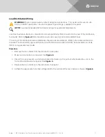
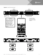
Страница 17: ...e size capacity and recommended torque The rating of the distribution device determines the wire size requirements Refer to the American National Standards Institute ANSI approved National Fire Protec...

Страница 18: ...AWG Recommended Torque 9 in lbs Rear rear cover removed for clarity only Rear Pull Out Wiring Guide OR Adhere the appropriate furnished label here OR Adhere the appropriate furnished label here WARNI...

Страница 19: ...ommended Input External Branch Circuit Protection Wire Sizes and Lug per side External Overcurrent Protection Device Rating Ambient Operating Temperature 1 Loop Length Ft 1 0 Voltage Drop 2 Recm 90 C...

Страница 20: ...n on side A d Feed B FA Indicator When illuminated red a distribution fuse is open on side B e MAJ When illuminated red a major alarm is active f MIN When illuminated amber a minor alarm is active 1 4...

Страница 21: ...nted at the front of this document Replacing a Distribution Fuse Replace distribution fuses with the same type and rating Procedure 1 Refer to Figure 3 and replace the fuse 2 Verify no alarms are acti...

Страница 22: ...wo captive fasteners and pulling the assembly from the unit Disconnect the internal wiring to the card by unplugging the connector when the circuit card is pulled out about half way 5 Remove the circu...

Страница 23: ...Vertiv 200 A Distribution Fuse Panel Assembly Installation User Manual UM563317 Rev B 23 Figure 9 Alarm Card Replacement Alarm Card Alarm Card Replacement Captive Fasteners Rear...

Страница 24: ...UM563317 RB 05 17...

Отзывы: