Vertiv
|
200 A Distribution Fuse Panel Assembly Installation & User Manual (UM563317)
|
Rev. B
16
Fuse Alarm
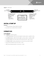
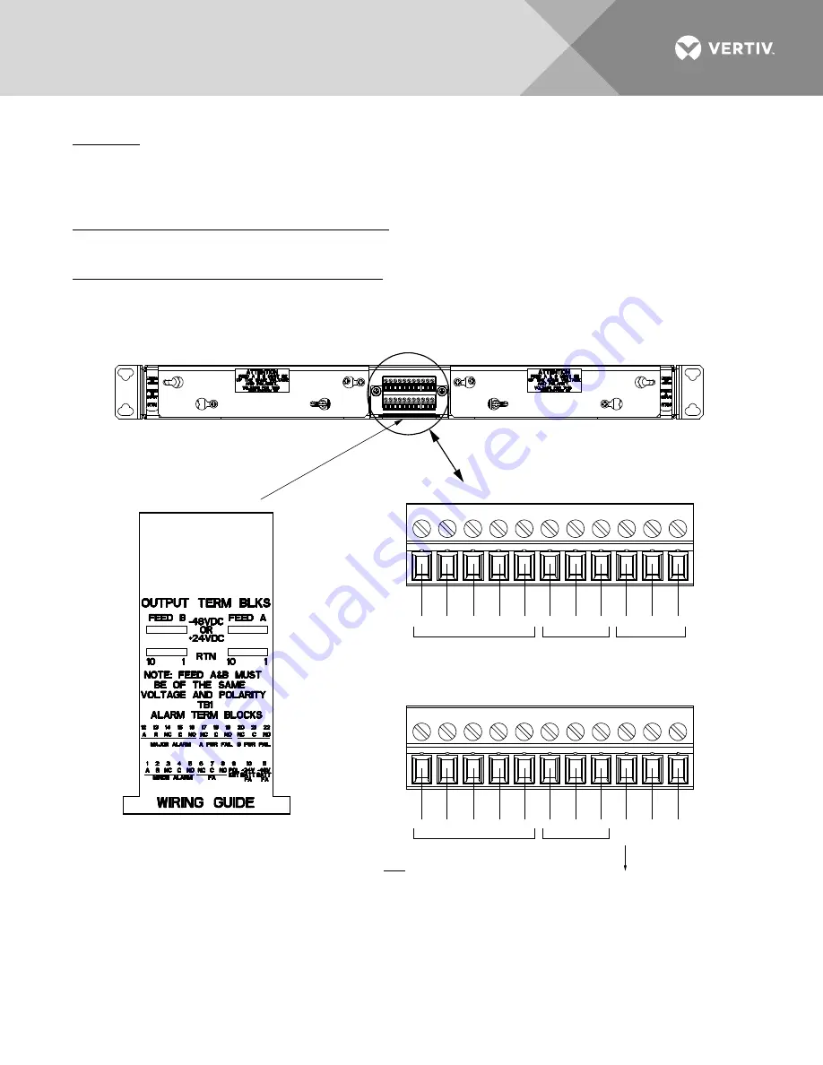
If a fuse in the distribution fuse panel opens, relay contacts open between terminals 6 and 7 of TB1 and relay
contacts close between terminals 7 and 8 of TB1. Normal operation provides closed relay contacts between
terminals 6 and 7 of TB1 and open relay contacts between terminals 7 and 8 of TB1.
+24V Battery Fuse Alarm (+24 VDC Installation Only)
If a fuse in the distribution fuse panel opens, +24 VDC is provided at terminal 10 of TB1.
-48V Battery Fuse Alarm (-48 VDC Installation Only)
If a fuse in the distribution fuse panel opens, -48 VDC is provided at terminal 11 of TB1.
Figure 5:
External Alarm Connections
TB1 (Top Terminal Block)
TB1 (Bottom Terminal Block)
Major Alarm
Minor Alarm
Pull Out Wiring Guide
FA
A PWR Fail
B PWR Fail
not
used
+24V
Batt
FA
-48V
Batt
FA
A R NC C NO NC C NO NC C NO
1 2 3 4 5 6 7 8 9 10 11
12 13 14 15 16 17 18 19 20 21 22
A R NC C NO NC C NO
TB1:
Wire Size Capacity: 28 to 16 AWG.
Recommended Torque: 2.2 in-lbs.
Relays shown in the deenergized state.
FA, Minor Alarm, and Major Alarm relays
are normally de-energized and energize
during an alarm condition.
A PWR Fail and B PWR Fail relays are
normally energized and de-energize during
an alarm condition.
Rear
Polarization key
installed in this position
so top removable half
and bottom removable
half cannot be inter -
changed.
Содержание NetSure NSFP200
Страница 24: ...UM563317 RB 05 17...


