4 CONTROLS AND INDICATORS
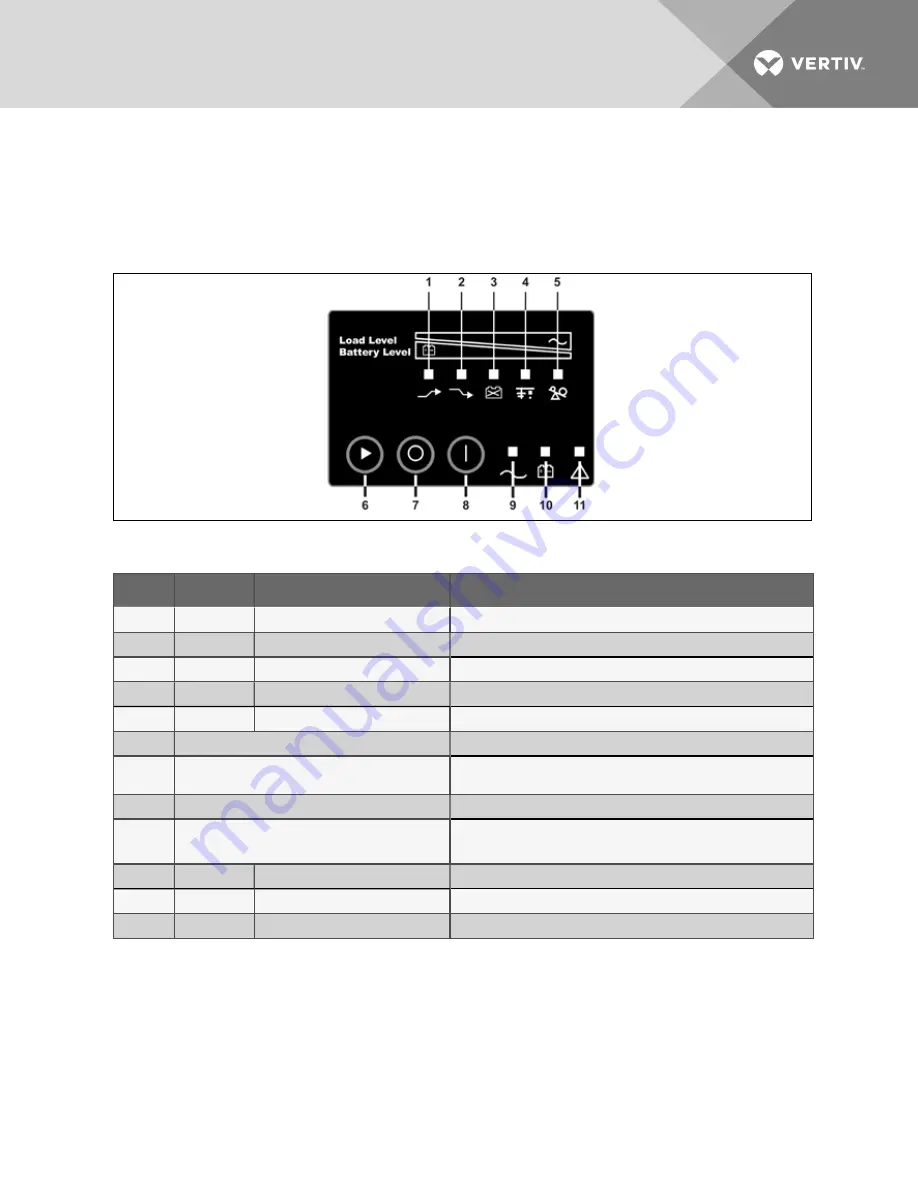
Buttons on the front panel display control the Liebert PSI XR. Eight LEDs on the panel indicate the UPS’s
status. Refer to Figure 4.1 below and Table 4.1 below.
Figure 4.1 Display and status indicators
Item
Status Indicators
Description
1
LED 1
AVR Boost
UPS Operation in AVR Boost Mode
2
LED 2
AVR Buck
UPS Operation in AVR Buck Mode
3
LED 3
Battery Condition
Battery Fault/Weak
4
LED 4
Grounding/Site Wiring Fault
UPS Grounding/Site Wiring Fault
5
LED 5
Overload
UPS Overload
1 to 5
Load/Battery Level
Indicate Load/Battery Level
6
Status Change Button
Switches Display from Load Level Indicators
to Battery Level Indicators
7
OFF Button
UPS Off
8
ON Button
Turn on UPS, Manual Self-Diagnostic (Normal Mode),
Silence Alarm (Battery Mode)
9
LED 9
Normal Mode
UPS Operation in Normal Mode
10
LED 10
Battery Mode
UPS Operation in Battery Mode
11
LED 11
UPS Fault
UPS Fault
Table 4.1 Display and status indicators function, legend
4.1 Control Buttons
4.1.1 On/Alarm Silence/Manual Self-Diagnostic Test
This button controls output power to connected load(s). It has three functions:
•
On
•
Alarm Silence
Vertiv
| Liebert® PSI XR™ User Manual |
17
Содержание Liebert PSI XR 1000
Страница 1: ...Liebert PSI XR 1000 1500 2200 3000 120VAC User Manual...
Страница 6: ...Vertiv Liebert PSI XR User Manual 2 This page intentionally left blank...
Страница 8: ...Vertiv Liebert PSI XR User Manual 4 This page intentionally left blank...
Страница 10: ...Figure 1 3 2200 and 3000VA rear view Vertiv Liebert PSI XR User Manual 6...
Страница 12: ...Vertiv Liebert PSI XR User Manual 8 This page intentionally left blank...
Страница 26: ...Vertiv Liebert PSI XR User Manual 22 This page intentionally left blank...
Страница 30: ...Figure 7 1 Battery replacement Vertiv Liebert PSI XR User Manual 26...
Страница 34: ...Vertiv Liebert PSI XR User Manual 30 This page intentionally left blank...
Страница 36: ...Vertiv Liebert PSI XR User Manual 32 This page intentionally left blank...
Страница 37: ......


