Chapter 2 Battery installation 15
LIEBERT APM UPS Module And Parallel System 30kVA~150kVA User Manual
Output System Connections
6. Connect the system output cables between the UPS output busbars (oA-oB-oC-N) and the critical load ensure
correct phase rotation. Tighten M6 Bolt to 5 Nm
Warning
If the load equipment will not be ready to accept power on the arrival of the commissioning engineer, then ensure that the system
output cables are safely isolated at their ends.
7. Re-install all the protective covers.
1.7 Control Cabling And Communication
1.7.1 Input and Output Interfaces
According to the specific needs of the field, the UPS may need auxiliary connection to realize the management of the
battery system (including external battery switch ad battery temperature sensor), communicate with PC, provide
alarm signal to external device, or realize remote EPO. These functions are realized through the UPS dry contact
located on the bypass module. The following interfaces are provided:
Back Feed Protection interface
External Battery Circuit Breaker interface
Battery ground fault detection
Battery temperature detection interface
Maintenance Bypass interface
Emergency Power Off interface
Service communication interface (for parameter setting and host monitoring)
Intellislots(TM) intelligent card interface
J8
J5
J10 J7
J6
J9
1
2
RS232
Intellislot 1
RS485
Intellislot 2
Intellislot 3
Fig.
1-4: Bypass Module (include Interfaces of dry contact and parallel signal board X2)
Note
All auxiliary cables must be double insulated twisted cables with cross sectional area of 0.5mm
2
~ 1.5mm
2
for maximum connection
length between 25m and 50m and must be routed separately from power cable
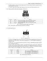
1.7.2 Back Feed Protection Interface (J5)
J5 is the backfeed protection interface, providing two relay output dry contact signals available to use with an
automatic device, externally located, to protect against back-feeding voltage thought the static bypass circuit.


