background image

54            Chapter 6 Operator Control And Display Panel 


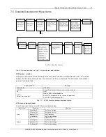
7.1.6   Default Screen 

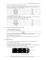
During UPS operation, if there is no alarm within two minutes, the default screen will appear, as shown in Fig. 


7-2 

After a short delay, the LCD backlight will turn off. Pressing any menu keys (F1 ~ F5) restores the default screen. 


按任意键返回主

菜单

LIEBERT NX

2008-10- 30

12: 30: 36

150kVA-3X3

并机系统

并机系统

并机系统

并机系统

(1#)

正常

正常

正常

正常

Parallel system

1(#)

Normal

Press any key to return to

the main menu

1#

Liebert NXr   150KVA

10:07:55

F1

F3

F4

F5

F2


Fig. 


7-3    Default screen 


7.2   Selecting Language 

The LCD menu and data display is available in 10 languages: Chinese, English, French, German, Italian, Polish, 
Portuguese, Russian, Spanish and Swedish. 

Use the following procedures to select the language:   

1. On the Output menu screen, press the F3 (left) or F4 (right) key to select the Language menu. 

2. Press the F5 (enter) key to move the cursor to the data window of the screen.   

3. Press the F3 (up) or F4 (down) key to select the desired language.   

4. Press the F5 (enter) key to confirm.   

5. Press the F2 (ESC) key repeatedly to return to the Output menu. At this point, the LCD displays in the selected 
language.   

7.3   Changing The Current Date And Time 

Use the following procedures to change the system date and time: 

1. On the Output menu screen, press the F3 (left) or F4 (right) key to select the Settings menu. 

2. Press the F5 (enter) key to move the cursor to the data window of the screen.   

3. Press the F3 (up) or F4 (down) key to select the Date & time item, and then press the F5 (enter) key to confirm.   

4. Press the F3 (up) or F4 (down) key to the row displaying the date and time, and press the F5 (enter) key to 
confirm. 

5. Use the F3 (up) or F4 (down) key to input the current date and time.   

6. Press the F5 (enter) key to confirm, and press the F2 (ESC) key to return to the Output menu.   

7.4   Control Password 

Password protection is used to limit the control functions accessible to the operator. The default password is ‘123456’. 
This password provides access to UPS and battery test functions. 

Содержание Liebert APM

Страница 1: ...Liebert APM User Manual 30 150kW Single Module and Parallel System AC Power For Business Critical Continuity ...

Страница 2: ...A For more details refer to Chapter 9 Continued compliance requires installation in accordance with these instructions and the use of manufacturer approved accessories only WARNING high earth leakage current Earth connection is critical before connecting the input supply include both utility supply and battery Earth leakage current introduced by the UPS in any configuration from 30kW to 150kW exce...

Страница 3: ... exists to any personnel when operating the equipment in the normal manner following the recommended operating procedures in this manual Battery voltage higher than 400Vdc All the battery maintenance and servicing procedures involving internal access need special tools or keys and should be carried out only by trained personnel SPECIAL CARE SHOULD BE TAKEN WHEN WORKING WITH THE BATTERIES ASSOCIATE...

Страница 4: ......

Страница 5: ...0 Cable Entry 11 1 5 External Protective Devices 12 1 5 1 Rectifier And Bypass Input Supply Of The UPS 12 1 5 2 External Battery 12 1 5 3 UPS Output 13 1 6 Power Cables 13 1 6 1 Cable Connections 14 1 7 Control Cabling And Communication 15 1 7 1 Input and Output Interfaces 15 1 7 2 Back Feed Protection Interface J5 15 1 7 3 External Battery Circuit Breaker Interface J6 16 1 7 4 Other input Interfa...

Страница 6: ...Internal Battery Module 35 Chapter 5 Operations 37 5 1 Introduction 37 5 1 1 Split Bypass Input 38 5 1 2 Static Transfer Switch 38 5 2 1 N Parallel System 38 5 2 1 Features Of Parallel System 38 5 2 2 Parallel Requirements Of UPS Rack Systems 39 5 3 Operating Mode 40 5 3 1 Normal Mode 40 5 3 2 Battery Mode 40 5 3 3 Auto Restart Mode 41 5 3 4 Bypass Mode 41 5 3 5 Black Start Mode 41 5 3 6 Maintenan...

Страница 7: ...ging The Current Date And Time 49 6 13 Control Password 50 Chapter 7 Operator Control And Display Panel 51 7 1 Introduction 51 7 1 1 Mimic Current Path 51 7 1 2 Audible Alarm Buzzer 52 7 1 3 Functional Keys 52 7 1 4 LCD And Menu Buttons 52 7 1 5 Primary Screen 53 7 1 6 Default Screen 54 7 2 Selecting Language 54 7 3 Changing The Current Date And Time 54 7 4 Control Password 54 7 5 Detailed Descrip...

Страница 8: ...ternal Battery Connections 29 Fig 4 3 150kVA UPS module system front view whit open door and back view without doors 30 Fig 4 4 Modular Battery Cabinet front view with open door and back view without doors 30 Fig 4 5 UPS External dimensions 31 Fig 4 6 Battery Cabinet External dimensions 31 Fig 4 7 UPS and BC bottom view show the position of casters and fixing holes 32 Fig 4 8 UPS and BC bottom vie...

Страница 9: ...r 3 52 Tab 7 5 Status description of inverter indicator 4 52 Tab 7 6 Status description of load indicator 5 52 Tab 7 7 Status description of status alarm indicator 6 52 Tab 7 8 Audible alarms descriptions 52 Tab 7 9 Functional keys Description 52 Tab 7 10 Icons of functional keys and the meanings 53 Tab 7 11 UPS information window Items description 55 Tab 7 12 UPS menu and data window Item descrip...

Страница 10: ...it breaker in accordance with relevant IT system standard WARNING battery hazards SPECIAL CARE SHOULD BE TAKEN WHEN WORKING WITH THE BATTERIES ASSOCIATED WITH THIS EQUIPMENT When connecting the battery the battery terminal voltage will exceed 400Vdc and is potentially lethal Eye protection should be worn to prevent injury from accidental electrical arcs Remove rings watches and all metal objects O...

Страница 11: ...e battery is above 40ºC then the battery service life will be decreased in exponent rate In a normal installation the battery temperature is maintained between 15 C and 25 C Keep batteries away from heat sources or air outlets If external batteries are to be used the battery circuit breakers or fuses must be mounted as close as possible to the batteries and the connecting cables should be as short...

Страница 12: ...be ship separate and cannot be with any battery modules installed 1 4 4 Clearances Required For Operating As LIEBERT APM series UPS has no ventilation grills at either sides no clearances are required for the sides To enable routine tightening of power terminations within the UPS it is recommended that clearance around the front of the equipment should be sufficient to enable free passage of perso...

Страница 13: ...r module 1 n 5 Requisite factory installed if n 3 4th and 5th module installed at site 5 Battery module 0 10 n Optional installed at site Tab 1 1 UPS configuration list 1 4 9 Installing Power Modules and Battery Modules The number and possible installation positions of the Power Modules and Battery Modules may vary according to the chosen factory configuration Thanks to the different mounting dept...

Страница 14: ... shown in Tab 1 2 Bit 1 Bit 2 Bit 3 Bit 4 Bit 5 Module address 1 0 0 0 0 1 0 1 0 0 0 2 1 1 0 0 0 3 0 0 1 0 0 4 1 0 1 0 0 5 Tab 1 2 DIP switch setting method 2 Place the ready switch on the front panel of the module to the up position i e in unready state 3 Insert the module in the installation position and push it into the cabinet 4 Secure the module to the cabinet through the fixing holes on both...

Страница 15: ...nsert the module in the installation position and push it into the cabinet 3 Secure the module to the cabinet trough the fixing holes on both side of the front panel of the module 1 4 10 Cable Entry Cables can enter the LIEBERT APM series UPS rack system and battery cabinet from below Cable entry is made possible through a blanking plate fitted at the bottom of the equipment The recommended instal...

Страница 16: ...d bypass input in the incoming mains distribution panel Note The rectifier input and bypass input must use the same neutral line Note For IT power network system 4 pole protective device must be installed on the external input distribution and external output distribution of the UPS Protection against earth faults RCD devices The RCD device installed upstream of the input supply should be Sensitiv...

Страница 17: ...eady state AC and DC Current Note 1 Input current of common input configurations of rectifier and bypass 2 Take special care when determining the size of the output and bypass neutral cable as the current circulating on the neutral cable may be greater than nominal current in the case of non linear loads which is usually 1 732 times of rated currents 3 Add 7 A per each redundant Power Module The e...

Страница 18: ...ction terminal strips are located The cabinet for the UPS must be connected to the user s ground connection Note The grounding cable and neutral cable must be connected in accordance with local and national codes practice Referring to Fig 4 11 Identify and make power connections for incoming cables according to one of the procedures below depending on the type of installation Common Input Connecti...

Страница 19: ...ctions are realized through the UPS dry contact located on the bypass module The following interfaces are provided Back Feed Protection interface External Battery Circuit Breaker interface Battery ground fault detection Battery temperature detection interface Maintenance Bypass interface Emergency Power Off interface Service communication interface for parameter setting and host monitoring Intelli...

Страница 20: ...rcuit Breaker Interface J6 12V OL GND FB DRV J6 12V 12V Fig 1 6 External BCB interface Position Name Descriptions J6 1 DRV BCB drive signal Hig BCB can be closed J6 2 FB BCB contact status Closed BCB is closed J6 3 GND Power supply GND J6 4 OL BCB online Input normally open This pin is closed to gnd when BCB interface signal is connected Tab 1 6 External battery circuit breaker interface 电池开关 BCB ...

Страница 21: ...n of the battery temperature sensor is shown in Figure 1 12 GND BAT OUT 12V BAT IN J8 Position Name Meaning J8 1 TMP_BAT_IN Internal battery temperature detection J8 2 12V_A 12V power supply J8 3 TMP_BAT_OUT External battery temperature detection J8 4 GND_A Power supply GND The external battery temperature sensor option is composed of a temperature probe and a temperature transmission board as sho...

Страница 22: ...r OFF EPO function This function can be activated by pressing a button on the control panel of the UPS or through a remote contact provided by the user The EPO pushbutton is protected by a hinged plastic cover As shown in Fig 1 10 J10 is the input interface for remote EPO The EPO is triggered when shorting pin 3 and pin 4 of J10 or opening pin 1 and pin 2 If external emergency stop functionality i...

Страница 23: ...xiliary cables must be double insulated twisted cables with cross sectional area of 0 5mm2 1 5mm2 for a maximum connection length between 25m and 50m 1 7 8 Other Interfaces J2 and J3 Parallel connection port is used for interacting parallel control signals between two UPS racks J4 LBS interface used to synchronize outputs of two UPS rack module systems Serial port RS232 2 A debug and maintenance p...

Страница 24: ...r has leakage replace it with new product Otherwise battery capacity reduction electric leakage or fire may be caused o Before operating the battery remove the finger ring watch necklace bracelet and any other metal objects o Wear rubber gloves and boots o Eye protection should be worn to prevent injury from accidental electrical arcs o Only use tools e g wrench with insulated handles o Do not lay...

Страница 25: ...d on shelves in a locked cabinet or dedicated battery room Note The battery modules regardless if they are mounted internally to the UPS or in the MBC make uses of strings of 30 batteries The Traditional external battery cabinet can make use of each even number of battery per string between 30 and 40 The default factory setting if the unit is ordered w o internal battery is 40 The cabinet is only ...

Страница 26: ...ld be insulated after its connection has been made Check if the battery is unexpectedly grounded If the battery is unexpectedly grounded remove the earth power supply Contacting any part of the grounded earth may be subject to electric shock Measure the battery voltage and carry out battery voltage calibration after the UPS is started WARNING Battery connections When using a traditional battery so...

Страница 27: ...al particularly Measure and record the air temperature in the battery room Check if the battery terminals are damaged or have the symptom of heating and if the shell or cover is damaged Please fasten every bolt on the terminal according to the fastening torque specified in the table below After 1 2 months of service recheck to make sure that each screw has been fastened according to the specified ...

Страница 28: ...ly open or normally closed dry contact signals 2 Normally closed EPO J10 terminals Pin 1 and pin 2 have been connected in factory and located on the parallel signal board X2 UPS1 UPS 1 J10 3 J10 4 1 3 4 UPS dry contact and parallel signal board X2 UPS 2 J10 3 J10 4 3 4 UPS dry contact and parallel signal board X2 J10 3 J10 4 3 4 UPS dry contact and parallel signal board X2 Fig 3 1 Circuit ram of e...

Страница 29: ...of each UPS module should be the same including the bypass input cables and UPS output cables so that the load sharing effect can be achieved in bypass mode 3 2 4 Control Cables Refer to Chapter 1 1 7 Parallel control cable The parallel control cable has THREE types in terms of length 5m 10m and 15m All the parallel cables are designed to be shielded and double insulated and are intended to be con...

Страница 30: ...s or parallel systems synchronized One system is set as the master unit and the other system is set as slave unit The LBS enables the load to have two independent UPS sources UPS1 UPS 6 UPS1 UPS 6 LBS STS UPS1 UPS UPS1 UPS LBS Connect to load Input rectifier Input rectifier Input rectifier parallel control cable parallel control cable Bypass Bypass Input rectifier Fig 3 4 Typical dual bus system w...

Страница 31: ...2 J2 J4 J3 X2 J2 J4 J3 X2 Dry contact and parallel signal board Rack module system UPS 1 Dry contact and parallel signal board Rack module system UPS 2 Dry contact and parallel signal board Rack module system UPS 3 Dry contact and parallel signal board Rack module system UPS n Fig 3 5 Typical dual bus system with LBS consisting of two 1 1 parallel system ...

Страница 32: ...28 Chapter 3 Installation Drawing Chapter 4 Installation Drawing Fig 4 1 Signal Wiring Diagram ...

Страница 33: ...CB Drive signal J6 2 FB BCB Contact status J6 3 GND Ground J6 4 OLBCB Online Input normally open This pin is active when BCB interface signal is connected BCB control board UHW242C2 Control and feedback X102 to J6 Bypass Module External battery temperature X108 to J8 Bypass Module Battery supply to X101 UV coil and auxiliary to X100 Battery temperature sensors X103 X104 X105 X106 ...

Страница 34: ...t open door and back view without doors 1 2 3 4 Fig 4 4 Modular Battery Cabinet front view with open door and back view without doors 1 Blanking plate 2 battery module 3 battery input 5 battery module CB 1 power module 2 Battery module 3 Bypass module 4 Power input output 5 Battery Module CB ...

Страница 35: ...apter 3 Installation Drawing 31 LIEBERT APM UPS Module And Parallel System 30kVA 150kVA User Manual 600 1996 1100 Fig 4 5 UPS External dimensions 600 1996 1100 Fig 4 6 Battery Cabinet External dimensions ...

Страница 36: ...pter 3 Installation Drawing 1081 340 DETAIL A 16 12 485 396 847 985 Fig 4 7 UPS and BC bottom view show the position of casters and fixing holes 460 80 Fig 4 8 UPS and BC bottom view show the cable entry area ...

Страница 37: ...Parallel System 30kVA 150kVA User Manual Fig 4 9 UPS and BC top view with open doors mN mC mB mA BAT BATN BAT PE bA bB bC mN oN oA oB oC Fig 4 10 AC and DC Connection 200 286 256 238 40 40 45 45 40 40 42 183 M8 all 203 25 Fig 4 11 UPS AC And DC Connection details ...

Страница 38: ...ter 3 Installation Drawing 269 183 25 80 80 40 M10 M8 Fig 4 12 MBC DC Connection details DSP control and detecting board U1 Main power board M1 Rectifier fan SCR Auxiliary power board M3 Fig 4 13 Power Module ...

Страница 39: ...n removing the modules remove the modules from top to bottom The purpose is to maintain the stable center of gravity 2 When inserting the module ensure that the Ready switch is in unready status 3 After inserting the module tighten all the screws before closing the ready switch 4 When removing the modules turn off the ready switch first remove the screws and then remove the modules 5 Wait for 5 mi...

Страница 40: ...batteries and each battery tray has one 50A DC current limiting circuit breaker The maximum discharging current of each layer of battery is 45A Over charging current will trip the circuit breaker and the monitoring unit will display the alarm Note When using modular battery it is important to install at least 2 battery module per each power module installed Not doing that will result in the CB tri...

Страница 41: ... double conversion power pulse width modulation PWM associated with full digital signal processing control DSP which features high reliability and convenience for use As shown in Fig 5 1 the AC input mains source is supplied at UPS input and converted into a DC source This DC source feeds the Inverter that converts the DC source into a clean and input independent AC source The battery powers the l...

Страница 42: ...cal load to be powered from the utility bypass supply while the UPS is shut down for routine maintenance Note When the UPS is operating in bypass mode or on maintenance bypass the connected electrical load is not protected from power failures or surges and sags 5 2 1 N Parallel System Several single unit UPS Rack Systems may constitute a 1 N system where up to four single units operate together fo...

Страница 43: ...eutral potential 3 Any RCD Residual Current detecting device if installed must be of an appropriate setting and located upstream of the common neutral bonding point Alternatively the device must monitor the protective earth currents of the system Refer to the High Leakage Current Warning in the first part of this manual 4 The outputs of all UPS Rack Systems must be connected to a common output bus...

Страница 44: ... requested for applications where sources do not share the same neutral reference or where the neutral is not available 5 3 Operating Mode The LIEBERT APM UPS is an on line double conversion reverse transfer UPS that permits operation in these modes Normal mode Battery Mode Auto restart mode Bypass mode Black start mode Maintenance mode manual bypass Parallel redundancy mode Sleep Mode 5 3 1 Norma...

Страница 45: ...or higher reliability or both the outputs of several UPS modules can be programmed for direct parallel a built in parallel controller in each UPS ensures automatic load sharing A parallel system can be composed of up to four UPS Rack Systems 5 3 1 Sleep Mode To improve system efficiency when system capacity is high and the load is light you can decide to automatically shut down a number of power m...

Страница 46: ... further battery discharge EOD is adjustable from 1 6V to 1 75V per cell VRLA 6 Battery Low Warning Time It is adjustable between 3 and 60 minutes The default is 5 minutes 5 4 2 Advanced Functions Software Settings Performed By The Commissioning Engineer Battery self test and self service At periodic intervals 20 of the rated capacity of the battery will be discharged automatically and the actual ...

Страница 47: ...0kVA User Manual Battery Disconnect Devices Alarm The alarm occurs when the battery disconnect device disconnects The external battery connects to the UPS through the external battery circuit breaker The circuit breaker is manually closed and tripped by the UPS control circuit ...

Страница 48: ...hapter 7 Operator Control And Display Panel for all the user operating keys and LED displays 2 The audible alarm may annunciate at various points in these procedures It can be cancelled at any time by pressing the SILENCE ON OFF push button 3 The UPS function can be set via maintenance software However the setting and commissioning must be done by maintenance engineers trained by Emerson 6 1 1 Pow...

Страница 49: ...tus Rectifier indicator Green Battery indicator Off Bypass indicator Off Inverter indicatorchp888 Green Output indicator Green Status indicator Green 6 2 2 Procedures For Switching Between Operation Modes Switch from normal mode to bypass mode Press inverter off button to switch to bypass mode Note In bypass mode the load is directly fed by the mains power instead of the pure AC power from the inv...

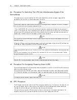
Страница 50: ...s Warning If you need to maintain the module wait for 10 minutes to let the DC bus capacitor fully discharge before removing corresponding module When the maintenance bypass switch is on position of ON some part of the UPS circuit still has hazardous voltage Therefore only qualified person can maintain the UPS Caution When the UPS is in maintenance bypass mode the load is not protected against abn...

Страница 51: ...is cleared perform the following procedures 1 Press FAULT CLEAR to reset the EPO status 2 Press INVERTER ON button on the right side of the operator and control panel for longer than 2s Note The rectifier will be turned on automatically when the overtemprature fault disappears at 5 minutes after the disappearance of overtemprature signals After pressing the EPO button if the UPS mains input has be...

Страница 52: ...ined user can perform the following procedures Maintenance guidance for power modules If the system is normal mode and the bypass is normal 1 If the UPS does not contain any redundant module press inverter off button on the front panel to manually power off the inverter and the UPS transfers to bypass 2 Disconnect the Ready switch of the main power module that needs maintenance or repair 3 Loosen ...

Страница 53: ...t the module Wait for 2 minutes 6 Press fault clear button if the bypass indicator in the mimic panel turns steady green it indicates that the bypass works normally 7 Insert the previously removed power modules confirm that the Ready switch of the power modules is in DISCONNECT status and then tighten the screws at the two sides of the power modules 8 Connect the ready switch of all power modules ...

Страница 54: ... the cursor to the display row of date and time and press F4 confirm 6 Press F2 move up and F3 move down to validate the current date and time 7 Press F4 confirm to validate the setting and press F1 ESC to return to the main menu 6 13 Control Password The system is password protected to limit the operator s operating and control authorities You can only operate and test the UPS and battery after e...

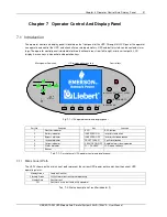
Страница 55: ...380 0 99 C CA 220 20 5 50 1 380 0 99 主路空开闭合 主路空开闭合 主路空开闭合 主路空开闭合 01 12 手动开机 手动开机 手动开机 手动开机 主路逆变供电 主路逆变供电 主路逆变供电 主路逆变供电 01 22 交流输出 交流输出 交流输出 交流输出 单机在线 NXr 150kVA 16 21 17 交流输出 A AB B BC C CA 相电压 V 相电流 A 频率 Hz 线电压 V 功率因数 220 220 220 20 5 20 5 20 5 50 1 50 1 50 1 380 380 380 0 99 0 99 0 99 F1 F2 F4 HELP Mimic power flow chart F3 Fig 7 1 UPS operator control and display panel Part No Function Key Func...

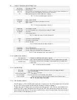
Страница 56: ...er Short single click The sound can be heard when any button is pressed 1 sec click with a 1 sec interval when system has general alarm for example AC fault this audible alarm can be heard Continuous alarm When system has serious faults for example fuse or hardware fault this audible alarm can be heard Tab 7 8 Audible alarms descriptions 7 1 3 Functional Keys EPO switch To cut off the load powerTo...

Страница 57: ...e primary screen is divided into four windows system information window data window menu window and keypad window The functions of the menu keys F1 F5 for the current screen are shown by self explanatory icons in the keypad window as appropriate From any menu on the primary screen pressing the F1 key returns to the Output menu Fig 7 2 Sections of the LCD and menu buttons Button ESC Home Exit Move ...

Страница 58: ...dow of the screen 3 Press the F3 up or F4 down key to select the desired language 4 Press the F5 enter key to confirm 5 Press the F2 ESC key repeatedly to return to the Output menu At this point the LCD displays in the selected language 7 3 Changing The Current Date And Time Use the following procedures to change the system date and time 1 On the Output menu screen press the F3 left or F4 right ke...

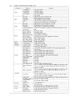
Страница 59: ...e Voltage Main PF Power factor L N Voltage V The Phase Voltage Frequency Hz The line line Voltage Bypass L L Voltage V The line line Voltage Language selection System Battery C Language Baud rate of serial port 1 Baud rate of serial port 2 Baud rate of serial port 3 Call back times Call back number 2 Call back number 3 Control password setting Main Phase current V Phase voltage A Frequency Hz Line...

Страница 60: ...Date Time Date Time Set Comm1 baud rate Communication baud rate setting of Intellislot 1 Comm2 baud rate Communication baud rate setting of Intellislot 2 Comm3 baud rate Communication baud rate setting of Intellislot 3 UPS address This setting is applicable to RS485 communication mode Communication Mode Communication Mode Callback Times Reserved Phone No 1 Reserved Phone No 2 Reserved Phone No 3 R...

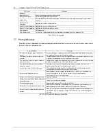
Страница 61: ...ins Voltage exceeds the upper or lower limit and results in rectifier shutdown Check the input phase voltage of rectifier Mains Undervoltage Mains Voltage is undervoltage with derated load Check the input line to line voltage of rectifier Mains Freq Abnormal Mains frequency is out of limit range and results in rectifier shutdown Check the input voltage and frequency of rectifier Rectifier fault Th...

Страница 62: ... load rises above 105 of nominal rating The alarm automatically resets once the overload condition is removed 1 Check which phase has overload through the load displayed in LCD so as to confirm if this alarm is true 2 If this alarm is true measure the actual output current to confirm if the displayed value is correct Disconnect non critical load In parallel system this alarm will be triggered if t...

Страница 63: ...he prompt information Unit Risk Off Confirm User press ENT key to shut down the UPS module in parallel system according to the prompt information Parallel System Risk Off Confirm User press ENT key to shut down the parallel system according to the prompt information Fault Reset Press the FAULT CLEAR Fault Reset button on the LCD panel Alarm Silence Press SILENCE ON OFF alarm silence key on the pan...

Страница 64: ...ds to Output Shutdown Confirm or Cancel No alternative supply is available and any Inverter Off operation will cause the load to be de energised Wait for User to Confirm or Cancel This operation leads to inverter overload confirm or cancel Turning off this inverter will lead to the overload of remaining inverter s in a parallel system Wait for User to Confirm or Cancel Turn on more UPS to carry cu...

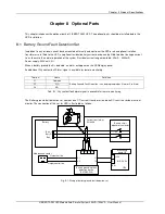
Страница 65: ...attery ground fault is detected an alarm will appear on the UPS display panel An additional Dry contact fault Alarm signal is available for remote monitoring Terminal Name Definition 21 Common 22 NC 24 NO Battery Ground Fault Detection can be programmed as Alarm or Pre Alarm Tab 8 1 Dry contact fault alarm signal is available for remote monitoring The Battery ground fault detection set contains on...

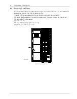
Страница 66: ...To replace each filter 1 Open the UPS front door and locate the filters on the back side of the front door see Fig 8 2 2 Remove one bracket and loosen the screw on the second bracket The second bracket need not be removed 3 Remove the dust filter to be replaced 4 Insert the clean filter 5 Reinstall the bracket tightening the screw securely 6 Tighten the screw on the second bracket 1 Fig 8 2 Replac...

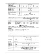
Страница 67: ...nd 60529 The APM output dynamic performances conforms the IEC62040 3 Class 3 9 2 PRODUCT SPECIFICATIONS Item Unit 30kW 90kW 150kW Acoustic noise level at 1 meter full load dB 53dBA 58dBA 62dBA Acoustic noise level at 1 meter half load dB 52dBA 56dBA 58dBA Altitude of Operation m 1000m above sea level derate power by 1 per 100m between 1000m and 2000m Relative Humidity 0 to 95 non condensing Operat...

Страница 68: ...perates at any of the rated supply voltages and frequencies without further adjustment 2 At 305V input mains the UPS maintains the specified output voltage at rated load without discharging a previously charged battery 3 EN 62040 3 50091 3 at rated load and input voltage 400V battery charged 4 EN 62040 3 50091 3 at rated load and input voltage 400V battery charging at maximum rated power 5 Add 4 5...

Страница 69: ...150 load 200ms Fault Current 310 141RMS Ampere each module short current limitation for 200msec then inverter is turned off Non linear load capability3 100 Neutral current capability 170 Steady state voltage stability 1 balanced load Transient voltage response4 5 THD 1 linear load 4 0 non linear load3 Synchronisation Window Rated frequency 2 Hz selectable 0 5 to 3Hz Max change rate of synch freque...

Страница 70: ...s voltage tolerance Vac Upper limit 10 15 or 20 default 15 Lower limit 10 20 30 or 40 default 20 delay time to accept steady bypass voltage 10 sec Bypass frequency tolerance 10 or 20 default 10 Synchronisation Window Hz Rated frequency 2 Hz selectable 0 5 to 3Hz Tab 9 8 Bypass input 1 Factory set to 400V 380 or 415V selectable by commissioning engineer 2 Factory set to 50Hz 60 Hz selectable by com...

Страница 71: ... quality materials of the part is outside the limits specified in SJ T11363 2006 Emerson Network Power Co Ltd has been committed to the design and manufacturing of environment friendly products It will reduce and eventually eliminate the harzardous substances in the products through unremitting efforts in research However limited by the current technical level the following parts still contain haz...

Страница 72: ...r Emerson Network Power Co Ltd has set up a service network and a recycling system for waste batteries so as to help the customers to dispose of the waste batteries properly Please obtain the recycling system of Emerson Network Power Co Ltd from the local Emerson office or nearest Emerson office If the customer does not accept this requirement or does not use the waste batteries recycling system s...

Страница 73: ...14 841 6598 Environmental Systems 800 543 2778 Outside the United States 1 614 888 0246 Locations United States 1050 Dearborn Drive P O Box 29186 Columbus Ohio 43229 United States Europe Via Leonardo Da Vinci 16 18 Zona Industriale Tognana 35028 Piove Di Sacco PD Italy Tel 39 049 9719111 Fax 39 049 5841 257 Asia 29 F The Orient Square Building F Ortigas Jr Road Ortigas Center Pasig City 1605 Phili...

Отзывы: