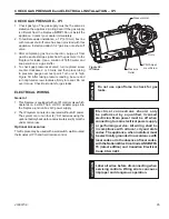
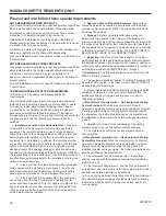

Pilot Shield
Figure 74
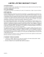
Figure 75
Figure 76
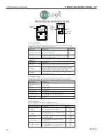
CFDV Series Gas Fireplace
46
20306739
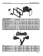
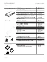
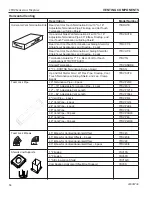
FIREGLASS AND STONE PLACEMENT
Your CFDV fi replace system is designed to be confi gured
in a traditional format (with logs) or a contemporary design
(using fi reglass and stones). You may elect to use only
fi reglass or a combination of fi reglass and stones. (The unit
is
not
designed to be operated with stones only. If you opt
to utilize the stones, you must also place fi reglass on the
burner.) The below instructions explain how to set up the
fi replace with fi reglass and/or fi reglass and stones. The
CKCFDV kit and/or GKB, GKD, GKO and GKS fi reglass
kits are designed for use with these instructions.
WARNING: Before beginning installation, turn off fi re-
place and allow to cool completely.
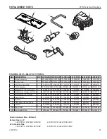
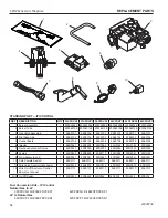
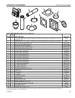
Kit contents:
• 16 Stones
• 1 Bag of Onyx Glass
• 1 Bag of Diamond Glass
• Pilot Shield
• 2 Screws
Tools required:
Phillips screwdriver, vacuum
CAUTION: Use gloves when handling glass pieces.
1. Remove the canopy above the glass frame by sliding
it forward. Set aside.
2. Remove the access panel located beneath the glass
frame by lifting it up and out of the unit. Set aside.
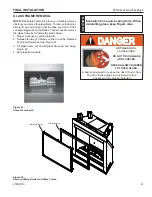
3. Remove the safety barrier by lifting up and pulling out.
Remove the glass frame assembly by releasing the
latches on top of the fi replaces and tilting frame for-
ward. Lift off and set aside.
4. Remove the logs if they are installed. Vacuum the rock
wool off the burner.
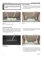
5. Remove the four (4) pin log plate assemblies by re-
moving the two (2) screws on each assembly. Discard.
NOTE
: There is a right front pin log plate assembly, a
left front pin log plate assembly and two (2) rear pin log
plate assemblies.
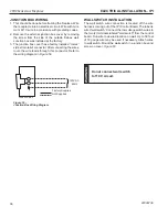
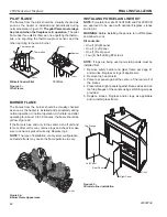
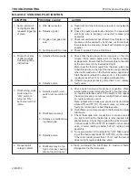
6. Loosen two (2) pilot screws.
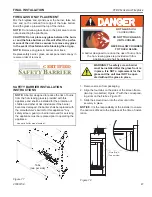
7. Install the extra pilot shield provided with the kit by slid-
ing it down between the front of the pilot and the burn-
er. Fasten the shield using the two (2) screws supplied
in kit.
Figure 74
8. Tighten screws that were loosened in Step 6.
FINAL INSTALLATION
W
ARNING
Turn off gas before servicing fi replace. It
is recommended that a qualifi ed service
technician perform these check-ups at the
beginning of each heating season.
NOTE:
The CFDV is designed to operate with either glass
only or with glass and stones.
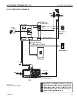
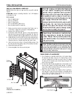
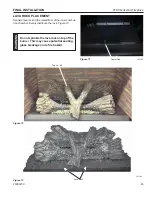
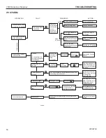
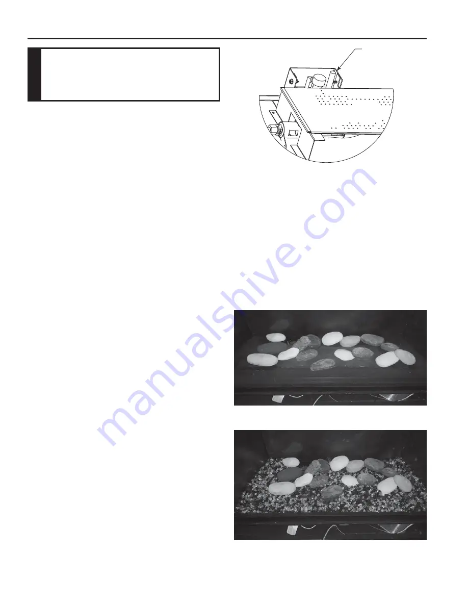
Glass & Stone Installation
Begin by placing stones randomly on the unported ar-
eas of the burner. Then place stones around the burner
and on top of the false hearth.
Figure 75
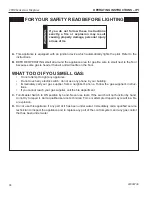
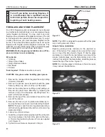
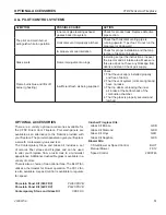
Mix the glass
and place it on top of the burner between and around the
stones. Sprinkle glass over the false bottom and on the
inclined front edge of the false bottom. Build the glass up
toward the top of the incline.
Figure 76
NOTE:
Do not allow glass to fall down in the pilot area as
it may obstruct the pilot fl ame.


