OWNER’S MANUAL
33
VERLINDE reserves the right to alter or amend the above information without notice
11/2018
15 - Appendices
A
- Diagram of limit switch………………………………………………………..p 34
TIRLIFT 2 250, 350 et 500 kg
TIRLIFT 2 600, 800, 990 et 1500 kg
B
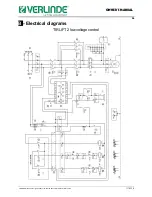
- Electrical diagrams…………………………………………………………….p 36
Important: the following diagrams correspond to a standard installation of our
standard models.
If the winch is adapted to a specific use, a specific electrical diagram is
required: do not hesitate to contact us to obtain this.
TIRLIFT 2 in low voltage control (single-phase/three-phase)
TIRLIFT 2 speed variation
C
- Exploded views and spare parts lists………………………………………..p 42
TIRLIFT 2 in low voltage control
TIRLIFT 2 – Variable speed models
TIRLIFT 2 803 NU 17_PECHE 400 V and 440 V
TIRLIFT 2 803 low voltage control 17_PECHE 400 V and 440 V
D
- Optional equipment……………………………………………………………p 49
End limit switches (speed variation and Low Voltage versions)
Trouble shooting hand wheel and brake release
Second rope clamp
Rope slack switch
Tubular frame
Grooved drum
Load limiter
Disengaging drum
Rocking winch


