background image


                              OWNER’S MANUAL


3


VERLINDE reserves the right to alter or amend the above information without notice 


11/2018 


1 -


Conditions of use 

 
All users must read the set-up instructions carefully before using the product for the first time. These 
instructions should enable the user to familiarise themselves with the winch and use it to its full 
capacity. The set-up instructions contain important information about how to use the winch safely and 
correctly. Compliance with these instructions helps to avoid danger, reduce repair costs, reduce 
stoppage time and improve the reliability and service life of the winch. The instruction manual must 
always be available in the place where the winch is being used. In addition to the set-up instructions 
and regulations concerning the prevention of accidents, the work safety and professional regulations 
in force in each country must also be respected. 
 
This equipment is governed by European regulations and more specifically Directive 2006/42/EC on 
machinery, EMC Directive 2004/108/EC and LVD 2006/95/EC, as well as the EN 14492/1 standard. 


These winches are designed to move loads using a suitable steel rope. They have been designed to 
perform  lifting  and  pulling  operations  within  the  defined  load  capacity  limit  and  with  safety  factor  5 
(static against sudden failure). 


  For  use  in  lifting,  the  European  regulation  makes  certain  equipment  obligatory,  such  as  a  limit 

switch system and, for loads of 1,000 kg or more, a load limiter. 

  The  operator  must  check  the  presence  of  this  equipment  (available  as  an  option  from  the 

manufacturer) before using the product for lifting purposes. 

  The  capacity  indicated  on  the  winch  corresponds  to  the  maximum  capacity  of  use  (MCU);  in  no 

event should this capacity be exceeded. 


T

HIS WINCH CAN UNDER NO CIRCUMSTANCES BE USED TO LIFT PEOPLE

  Do  not  begin moving the  load  until  you  have  attached  it  correctly  and checked that  all  personnel 

are outside the danger zone. 

  Before use, the operator must always check that the machine, rope, hook, markings and moorings 

are in good working order. 

  The operator must check that the load is attached in such a way that the winch, the rope and the 

load place neither the operator nor any other person is in danger. 

  The  winches  can  be  used  at  ambient  temperatures  ranging from  -10°C to  +50°C.  Please  consult 

the manufacturer in the event of extreme conditions of use. 
Important: In the event of an ambient temperature below 0°C, the brake must be tested to ensure that 
there are no operating faults resulting from the freezing conditions. 

  The data concerning the heat-resistance of the steel rope and its fastenings must be available on 

request from the manufacturer and must be respected. 

  VERLINDE cannot accept any liability for the consequences resulting from the use or installation of 

equipment  not  provided  for  in  the  present  instructions  or  for  the  consequences  of  removal, 
modification  or  replacement  of  original  parts  or  components  with  parts  or  components  from  other 
sources without the written agreement of VERLINDE. 

  The use of winches requires strict compliance with the accident prevention and safety measures in 

force in the country where they are used. 


YOU MUST ALSO RESPECT THE REGULATIONS APPLICABLE IN YOUR COUNTRY. 


Содержание TIRLIFT 2

Страница 1: ...VERLINDE reserves the right to alter or amend the above information without notice 11 2018 Owner s Manual Electric winches 250 to 1500 kg English ...

Страница 2: ...ription 6 2 Operation 6 3 Available models 6 4 Dimensions and fastenings 6 5 Accessories 6 6 FEM classification 6 7 Variable speed drive 7 Handling Storage p 14 8 Assembly and start up p 14 8 1 Securing the winch 8 2 Wire rope exits 8 3 Change to initial assembly 8 4 Set up 8 5 Electrical connections 9 Servicing and maintenance p 26 9 1 Winches 9 2 Ropes 9 3 Hooks 9 4 Brake 10 Taking out of use p ...

Страница 3: ...quipment available as an option from the manufacturer before using the product for lifting purposes The capacity indicated on the winch corresponds to the maximum capacity of use MCU in no event should this capacity be exceeded THIS WINCH CAN UNDER NO CIRCUMSTANCES BE USED TO LIFT PEOPLE Do not begin moving the load until you have attached it correctly and checked that all personnel are outside th...

Страница 4: ...tee HSC of your company if one exists Scrupulously respect all information in the sections concerning the CONDITIONS OF USE section 1 and the WORK ROPE section 8 5 4 The operator s must have an unimpeded view of the load Please ensure that the operator is qualified to operate the machine in the conditions provided for in this manual This will ensure the safety of both people and the environment Do...

Страница 5: ...ised as faulty after inspection by the qualified and approved department all free of charge The warranty excludes all other services or compensation Repairs undertaken within the scope of the warranty are in principle performed in the seller s workshops or the workshop of a representative approved by the manufacturer When work is carried out on the equipment outside of their workshops the seller m...

Страница 6: ...tests The commissioning or recommissioning inspections in the event of a change in the place of use the configuration or the conditions of use on the same site following the disassembly and subsequent reassembly of the lifting machine after any major replacement repair or transformation concerning the essential components of the lifting machine or following any accident caused by the failure of an...

Страница 7: ...te control with socket IP 65 220 380 V three phase control IP 55 double insulation Speed variation versions only 190 V direct control electromagnetic brake Electrical equipment under watertight cover Very low voltage 24 V remote control IP 65 6 2 Operation The load and winding speed of the rope on the drum are obtained by reducing the rotation movement of the electric motor via a shaft mounted hel...

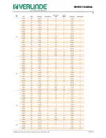
Страница 8: ...OWNER S MANUAL 8 VERLINDE reserves the right to alter or amend the above information without notice 11 2018 6 3 Available models ...

Страница 9: ...OWNER S MANUAL 9 VERLINDE reserves the right to alter or amend the above information without notice 11 2018 ...

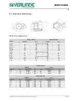
Страница 10: ...According to motors see table M mm 121 5 121 5 152 152 N mm 121 5 121 5 152 152 T mm 230 345 290 435 TIRLIFT 2 250 500 Standard Long Motor kW A mm L without with limit switch mm H mm A mm L without with limit switch mm H mm 0 75 451 356 421 284 5 451 468 533 284 5 1 1 462 356 421 284 5 462 468 533 284 5 2 2 473 487 5 487 5 306 5 473 468 533 306 5 TIRLIFT 2 600 1500 Standard Long Motor kW A mm L wi...

Страница 11: ...o motors see table M mm 121 5 121 5 152 152 N mm 121 5 121 5 152 152 T mm 230 345 290 435 TIRLIFT 2 250 500 Standard Long Motor kW A mm L without with limit switch mm H mm A mm L without with limit switch mm H mm 0 75 475 356 421 345 475 468 533 345 1 1 475 356 421 345 475 468 533 345 2 2 475 488 487 5 345 475 468 533 345 3 3 477 488 488 345 475 468 533 345 TIRLIFT 2 600 1500 Standard Long Motor k...

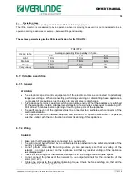
Страница 12: ...s the extent to which the lifting machine is used at maximum load or with a reduced load There are four different duty factors Light Lifting machines rarely subject to maximum load and regularly used for very light loads k 0 5 Medium Lifting machines quite often subject to maximum load and regularly used for light loads 0 5 k 0 63 Heavy Lifting machines often subject to maximum load and regularly ...

Страница 13: ...is switched off these capacitors retain a dangerous voltage for a few minutes subsequent to switching off Wait at least 5 minutes before opening or touching live parts of the appliance The earth connection of the appliance must be connected to a suitable earth connector of the electrical installation This appliance must be installed adjusted and serviced by a qualified electrician This person must...

Страница 14: ...installation site may lead to serious accidents To assess the suitability of the place of installation and its resistance to loads you must take into account any possible overloading the weight of the winch itself and the weight of the options and or accessories fitted to it including all dynamic forces The winch user is responsible for determining the place of installation If in doubt with regard...

Страница 15: ...8 8 2 Wire rope exits Key Standard exit right hand laid wire rope Non standard exits left hand laid wire rope IMPORTANT Use of the standard rope clamp on the limit switch side A non standard output can be made into a standard one by using the second rope clamp as long as this is known when placing the order ...

Страница 16: ...chine Any use which contravenes our instructions may create hazards In this case the manufacturer cannot accept any liability Do not use this machine before having read and understood the instruction manual in its entirety Always keep the manual close to the machine available to the operator and the maintenance staff Comply and ensure compliance with the safety rules Connect to the power supply se...

Страница 17: ...es the right to alter or amend the above information without notice 11 2018 To ensure correct winding of the rope the distance between the deflecting pulley and the drum must equal to or be greater than 20 times the length of the drum ...

Страница 18: ... mm 5 5 kW 400 V tri 3 T 1 5 mm 1 5 mm 0 75 1 1 kW 3 T 1 5 mm 2 5 mm 2 2 3 kW 3 T 2 5 mm 4 0 mm 5 5 kW Power supply via a generator is possible minimum power in kVA equal to or greater than five times the motor power in kW 8 5 2 Connection IMPORTANT ALWAYS ENSURE THE POWER SUPPLY IS SWITCHED OFF BEFORE CONNECTING THE WINCH Main circuit breaker on the cut line Socket connection The appliance is sys...

Страница 19: ...ction of rotation Reminder check the maximum capacity of the winch Very important The safety regulations require that two to three whorls of rope always stay on the drum To comply with the legislation the rope diameter must not exceed the recommended diameter If the rope and the hook used were not supplied with the machine by the manufacturer check that they guarantee a level of safety correspondi...

Страница 20: ...s Never use a rope with faults such as an unacceptable number of broken strands basket distortions broken bird caging flattening constrictions strand extrusions broken rope cores slack strands bends or loops Always check the level of wear of the rope before use Never use steel ropes as loops Never expose steel ropes to angular or sharp edges Unwinding the rope from its reel CORRECT INCORRECT ...

Страница 21: ...cted Winding the rope on the drum Reminder the maximum capacity of these winches varies on each model see section 6 3 Very important The safety regulations require that 3 whorls of rope always stay on the drum To comply with the legislation the rope diameter must not exceed 7 mm for the TIRLIFT 2 250 350 500 or 12 mm for TIRLIFT 2 600 800 990 1500 If the rope and the hook used were not supplied wi...

Страница 22: ...r from crushing and premature flattening caused by the loaded upper layers Even if the first layer is wound correctly during installation it will expand a little while in service When the first layer expands loss of pre tension the initial procedure MUST be performed at regular intervals Otherwise the hard turns will severely crush the base layers Whatever you do DO NOT pass the rope through a cla...

Страница 23: ...the above information without notice 11 2018 Principle of reeving 8 5 4 Adjusting the limit switch A Clock type Remove the protective cover of the device inside this cover you will find the diagram below The levers which are now accessible can be turned manually Up ...

Страница 24: ...t position of the rotation circle where it activates the switch 3 Adjustment of the unwinding stop point bottom limit switch Unwind the rope to the maximum desired unwinding point Stop the winch Still in this position manually move the black lever 1 to the lowest position of the rotation circle where it activates the switch 3 B Type with IP 65 cam Remove the protective cover of the device the cams...

Страница 25: ...pe until the bottom point always leaving 3 safety turns on the drum Stop the winch Still in this position with the help of a suitable screwdriver turn the adjustment screw 2 until a click is heard in the contactor This range of limit switches also includes a model with 4 positions If you need more positions do not hesitate to consult us C Rotating cam limit switch IP66 67 Before doing anything tur...

Страница 26: ...pter 5 Obligatory regulatory checks by the user Check that the mechanical components are well lubricated during each periodic general inspection Renew the grease every 100 hours or every three years FUCHS Renolit CXI2 grease Very important Contact our after sales service in the event of a change in the type of grease 9 2 Ropes The wire ropes must be cleaned and greased regularly using a special gr...

Страница 27: ...d nuts Key 1 Cheese head screw 2 Adjusting nut 3 Frame 4 Pressure springs 5 Hub 6 Friction lining 7 Friction pad 8 Induction material 9 Manual release optional Operating principle On starting the motor the internal magnetic field opens the brake by lifting the conical plate from the friction surface at the bottom of the motor On stopping the motor the magnetic field disappears The central spring c...

Страница 28: ...x 0 8 mm Remove the cover and the fan Loosen the three screws by a few turns Turn the ring nut anti clockwise 30 0 12 mm to reduce the air gap Tighten the three screws Reposition the fan and its cover Key Cover Fan Screw Ring nut Cap Self locking nut Air gap 10 Taking out of use If the equipment is in a state of disrepair likely to give rise to risks it must not be used and must be taken out of se...

Страница 29: ... notice that certain parts of your winch need to be replaced use VERLINDE original parts only For all spare parts orders please indicate the following specifications on your order The type and capacity of the winch indicated on the nameplate The serial number and year of manufacture indicated on the nameplate The designation of the desired parts exploded views ...

Страница 30: ...upply cables Eliminate the short circuit Short circuit in the motor Have the fault corrected in an approved workshop Power supply cables incorrectly connected Correct the connection Motor earth fault Have the fault corrected in an approved workshop Speed greatly reduced when loaded Voltage drop Increase the power supply cable section Motor too hot temperature measure Insufficient ventilation Clear...

Страница 31: ...ight to alter or amend the above information without notice 11 2018 13 Tests This winch has been tested in the factory in a dynamic situation with a coefficient of 1 1 in a static situation with coefficient 1 25 14 Declaration of EC conformity ...

Страница 32: ...OWNER S MANUAL 32 VERLINDE reserves the right to alter or amend the above information without notice 11 2018 ...

Страница 33: ...l diagram is required do not hesitate to contact us to obtain this TIRLIFT 2 in low voltage control single phase three phase TIRLIFT 2 speed variation C Exploded views and spare parts lists p 42 TIRLIFT 2 in low voltage control TIRLIFT 2 Variable speed models TIRLIFT 2 803 NU 17_PECHE 400 V and 440 V TIRLIFT 2 803 low voltage control 17_PECHE 400 V and 440 V D Optional equipment p 49 End limit swi...

Страница 34: ...hexagonal nut 6 2 Tie 7 1 Pin stop bush ref EM 32 180 17 4 8 1 17 tooth black sprocket wheel 9 1 48 tooth black sprocket wheel 10 5 45 tooth grey sprocket wheel 11 5 20 tooth grey sprocket wheel 12 2 TRUARC 5 6 ring 13 1 Limit switch finger support 14 1 Red limit switch finger 15 2 Stop washer 16 1 Green limit switch finger 17 2 Curved washer Ø15x20x2 18 1 Washer M Ø10 19 1 Locked bottom nut M10 2...

Страница 35: ...et wheel 10 7 M1 45 tooth sprocket wheel 11 4 m1 20 tooth sprocket wheel 12 2 TRUARC 5 6 ring 13 1 Limit switch finger support 14 1 Red limit switch finger 15 2 Stop washer 16 1 Green limit switch finger 17 2 Curved washer Ø15x20x2 18 1 NF E 25 514 M Ø10 washer 19 1 NF E 25412 M10 locked bottom nut 20 2 M3 x 30 MF steel spacer stud 21 2 Contactor 22 2 NF E 25 125 M3x25 CHC screw 23 2 Captive nut 2...

Страница 36: ...OWNER S MANUAL 36 VERLINDE reserves the right to alter or amend the above information without notice 11 2018 B Electrical diagrams TIRLIFT 2 low voltage control ...

Страница 37: ...pty fuse holder mandatory 4 500 Ma 500 V 50 Hz single phase fuse 5 24 V 1 6 A secondary circuit fuse Option 6 Motor thermal protection 7 Single phase 230 V motor capacitor 8 230 400 V 50 Hz three phase motor 9 24 V DC mechanical brake 10 Raising control box 11 Lowering control box 12 Emergency stop control box 13 Control unit caravan socket 14 Upper limit switch 15 Lower limit switch Option 16 Rop...

Страница 38: ...OWNER S MANUAL 38 VERLINDE reserves the right to alter or amend the above information without notice 11 2018 TIRLIFT 2 speed variation 230 V single phase ...

Страница 39: ...OWNER S MANUAL 39 VERLINDE reserves the right to alter or amend the above information without notice 11 2018 TIRLIFT 2 speed variation 230 V single phase continuation ...

Страница 40: ...OWNER S MANUAL 40 VERLINDE reserves the right to alter or amend the above information without notice 11 2018 TIRLIFT 2 speed variation 400 V three phase ...

Страница 41: ...OWNER S MANUAL 41 VERLINDE reserves the right to alter or amend the above information without notice 11 2018 TIRLIFT 2 speed variation 400 V three phase continuation ...

Страница 42: ...crew 02 2 6304 2RS bearing 15 1 NBR seal Ø3 03 2 Pin 5x20 16 1 Transmission cover 04 1 1 1 kW three phase motor electromagnetic brake 17 13 M6x16 CHC screw 05 1 Spacer 18 3 Tie 06 4 M6x25 CHC screw 19 1 Protective grate 07 1 99 tooth wheel 20 1 External casing 08 1 6x6 key 21 3 M10x40 CHC screw 09 1 16 tooth sprocket wheel 22 1 Box mounting 10 2 6206 2RS bearing 23 2 M5x10 STAINLESS STEEL hex sock...

Страница 43: ...x socket button head screw 4 1 Motor 24 1 Limit switch 5 2 Spacer 25 1 Electrical unit cover 6 17 M8x30 CHC screw 31 1 Spacer 7 1 Wheel 32 2 6004 2RS bearing 8 1 6x6x15 key 33 1 Wheel 9 1 Sprocket wheel 34 1 Sprocket wheel 10 1 6210 2RS bearing 42 1 Sprocket wheel 11 1 Drum 43 1 8x7x20 key 12 1 Wheel 44 1 External retaining ring 90x3 13 1 Washer 45 1 Watertight ring 14 1 M16 30 hex head screw 46 1...

Страница 44: ...earing 15 1 NBR seal Ø3 03 2 Pin 5x20 16 1 Transmission cover 04 1 1 1 kW three phase motor electromagnetic brake 17 13 M6x16 CHC screw 05 1 Spacer 18 3 Tie 06 4 M6x25 CHC screw 19 1 Protective grate 07 1 99 tooth wheel 20 1 External casing 08 1 6x6 key 21 3 M10x40 CHC screw 09 1 16 tooth sprocket wheel 22 1 Box mounting 10 2 6206 2RS bearing 23 2 M5x10 STAINLESS STEEL hex socket button head screw...

Страница 45: ...ex socket button head screw 4 1 Motor 24 1 Limit switch 5 2 Spacer 25 1 Electrical unit cover 6 17 M8x30 CHC screw 31 1 Spacer 7 1 Wheel 32 2 6004 2RS bearing 8 1 6x6x15 key 33 1 Wheel 9 1 Sprocket wheel 34 1 Sprocket wheel 10 1 6210 2RS bearing 42 1 Sprocket wheel 11 1 Drum 43 1 8x7x20 key 12 1 Wheel 44 1 External retaining ring 90x3 13 1 Washer 45 1 Watertight ring 14 1 M16 30 hex head screw 46 ...

Страница 46: ...er circlips 90x3 30 2 3451 Ball bearing 6 001 2RS 10 1 3051 Sealed bearing ring 55_90_10 31 2 13569 Screw F HC M8x30 11 1 24455 Machined transmission case 32 1 20736 Sub unit TRB PC 12 1 24454 Machined bored motor transmission casing 0110 33 1 52542 Sub unit U tie and welded nuts 13 1 24456 Machined outer casing 34 2 52916 PC riser 14 1 3972 Joint 03 lg 1263mm 35 2 356 20 44 REF 356 BLUE MEDIUM LO...

Страница 47: ...20734 PC and MDC spacer 13 1 24456 Machined outer casing 45 1 20737 Roller 14 1 3972 Joint 03 lg 1263mm 46 1 20738 Shaft 15 2 3217 Pin DIN EN ISO 8742 5x20 47 2 3451 Ball bearing 6 001 2RS 16 3 13157 Screw C HC M12x50 48 2 13569 Screw F HC M8x30 17 1 3207 7B socket 49 1 20736 Sub unit TRB PC 18 1 2001 Verified VERLINDE plate 50 1 52542 Sub unit U tie and welded nuts 19 2 3290 Metal gland PG11 51 2...

Страница 48: ...OWNER S MANUAL 48 VERLINDE reserves the right to alter or amend the above information without notice 11 2018 42 ...

Страница 49: ...ws you to lift a load using several ropes or facilitates a two way system Rope slack switch This automatically stops the winch when the rope is not taut for example during descent when an obstacle is blocking the load If the rope output angle is changed the positioning of the electrical contact can be adjusted by turning the screw Tubular Frame TIRLIFT 2 250 to 500 kg The TIRLIFT 2 with tubular fr...

Страница 50: ... use the setting must be readjusted In the event of overloading of the winch a load limitation by motor current measurement cuts the lift control Once you have identified and eliminated the cause of the load limiter activation use the key activated turning button on the right of the unit to reset the load limiter and use the winch again Adjust the sensitivity of the load limiter by adjusting the I...

Страница 51: ...ury WARNING UNEXPECTED OPERATION OF THE EQUIPMENT This product must not be used in the capacity of the critical functions of a safety machine Wherever there is a risk to the personnel and or equipment use the appropriate hard wired safety lugs Please do not disassemble repair or modify the product Respect the installation and operating conditions of the product described in this document Non compl...

Страница 52: ...aximum using the up button then press save 6 Press the browse button until D001 is displayed 7 Press the up button until D002 is displayed current reading in ampere 8 Press save button 0000 is displayed Load winch at the required stop value 9 Activate lifting direct ampere reading For example 5 A at XX kg stop required 10 Return to C041 using the save button then browse save and press up Adjust to...

Страница 53: ... until C041 is displayed 5 Press the value in ampere is displayed press until the maximum value then press to confirm 6 Press returns to C041 then press the button three times for C 7 Press for D002 then press 0000 is displayed direct ampere reading 8 Load the winch at the required value then test and take ampere reading e g 5 00 A 9 Return to C041 to adjust the value determined in D002 press pres...

Страница 54: ...plied to the rope Systematically verify that all tension has been removed from the rope before performing the operation This can be done by pulling the control button Ref 3 21706 outwards The disengaged position is maintained by turning the button by one quarter of a turn The drum is re engaged by turning the button by a further quarter of a turn and allowing the drum to rotate freely When the con...

Страница 55: ...gaging button 4 1 21705 Disengaging cover 5 1 20926 Disengaging spring 6 3 13014 H FR M8 nut 7 3 20043 AXK2542 needle thrust bearing 8 2 13572 8x20 fluted pin 9 2 13571 24x1 2 ext retaining ring 10 3 13123 8x26 fluted pins 11 6 NF EN ISO 8745 8 x 26 C HC M5x16 screw 12 6 20044 AS2542 thrust washer 13 3 23960 Disengaging pawl 14 1 23959 Block 15 1 23955 Fluted hub 16 1 23957 Compression washer 17 1...

Страница 56: ...ple As a result the conditions necessary for its proper operation are Sufficient constant tension on the rope to make the device move during winding and unwinding This condition can easily be achieved in lifting operations by installing an appropriately dimensioned counterweight at the end of the rope Free movement of the mobile unit which means Perfectly horizontal installation of the chassis No ...

Страница 57: ...7 M10 30 hex head screw 16 6 ISO 4018 M8x20 ISO 4018 M8 x 20 hex head screw 17 1 57777 Machined cogged plate 18 1 57799 SE_upper support 32 4 57805 Roller 33 4 2964 6003 2RS RN ball bearing 23 1 57788 Reinforcement 24 1 57789 Symmetrical reinforcement 25 1 57235 Tensioner 26 4 13075 ISO 4017 M10 25 hex head screw 28 10 13210 NF E 25 514 M Ø8 washer 30 5 ISO 10642 M8 x 40 Flat countersunk head sock...

Страница 58: ...4 13060 ISO 4017 M6 25 hex head screw 3 9 13703 ISO 7380 M5 x 16 stainless steel hex socket flattened half round head screw 17 2 13062 ISO 4017 M6 35 hex head screw 4 4 13076 ISO 4017 M10 30 hex head screw 18 2 13010 NF E 24032 M6 nut 10 1 57798 SE_moving table 19 4 58007 Shim 12 1 57845 Smooth rack plate 20 1 58006 SE_Tensioner rail 13 1 57846 Cogged rack plate 21 2 13018 NF E 24032 M10 nut 15 4 ...

Отзывы: