AC300 Series Vector Control Inverter Manual
Function Parameter Specifications
132
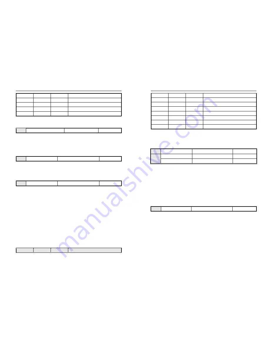
OFF ON ON Terminal
AI
analog
ON OFF OFF Terminal
AS
current
analog
ON
OFF
ON
Terminal PUL pulse signal
ON ON OFF RS485
communication
ON ON ON Optional
card
Any doubt please see "FC" parameter group which is about multispeed time sequence.
F11.01
Keyboard number PID given/feedback
Setting range: 0.00-100.0%
Factory set: 50.0%
This function is valid only when
[F11.00]
/
[F11.03]
is set as keyboard number given/feedback. After this parameter is
changed, PID given in monitor object is modified automatically at the same time.
If
[F11.09]
LED “0” is set as 2, this value can be modified by UP/DW key. Whether save the modification is decided
by
[F04.09
] LED “00” digit.
F11.02
PID given changing time
Setting range:0.00-60.00 Factory
set:1.00s
PID given changing time:
the ratio of
PID given changing time from 0.0% to 100.0% .While PID given changes,PID given changes in linear line
by the given time to reduce the bad influence of given surge.
F11.03
PID feedback signal source
Setting range:0-9
Factory set:2
Set the input channel of the PID controller feedback signal.
0: Keyboard digital PID feedback
The PID feedback channel is determined by the setting value of [F11.01].
1: reserved
2: Voltage/current analog AI1 feedback
The PID feedback channel is the voltage/current analog AI1.
3: Voltage/current analog AI2 feedback
The PID feedback channel is the voltage/current analog AI2.
4: Reserved.
5: Terminal pulse PUL feedback
The PID feedback channel is the terminal pulse PUL.
6: RS485 communication feedback
The PID feedback channel is RS485 communication, and the communication
address is 0x3009/0x2009.
7: Optional card
The PID feedback channel is an optional card. For details, refer to the optional card manual.
8: Terminal selection
The PID feedback channel is selected by the combination of multi-function input terminals. The
multi-function input terminal is set by [F02.00~F02.09].
9: Communication given active current
Terminal switch table:
Terminal 3
Terminal 2
Terminal 1
PID giving terminal switch selection
AC300 Series Vector Control Inverter Manual
Function Parameter Specifications
133
OFF
OFF
OFF
Keyboard number give PID
OFF OFF ON Keyboard
potentiometer
OFF
ON
OFF
Terminal AI1 voltage analog
OFF ON ON Terminal
AI
analog
ON OFF OFF Terminal
AS
current
analog
ON
OFF
ON
Terminal PUL pulse signal
ON ON OFF RS485
communication
ON ON ON Optional
card
Any doubt please see "FC" parameter group which is about multispeed time sequence.
Note: The PID signal source and PID controller feedback signal source cannot be set to the same channel,
otherwise the PID will not work normally.
F11.04
Feedback signal filter time
Setting range: 0.000-6.000s
Factory set: 0.010s
F11.05
Feedback signal gain
Setting range: 0.00-10.00
Factory set: 1.00
F11.06
Given and feedback range
Setting range: 0-100.0
Factory set: 100.0
Feedback signal filter time:
Filter the feedback signal to eliminate to the disturb. The longer filter time is,the stronger anti-disturb force is,but the
slower feedback response is.
Feedback signal gain:
It is used to linearize the feedback input signal.
Given and feedback range:
PID given and feedback don’t have the unit to adjust the PID given (C-08) and PID feedback display(C-09).PID given
and feedback 100.0% corresponds with the given and feedback range[F11.06].For example,[F11.06]is set 80.0,if the
PID given 50.0%, and then PID given display C-08 is 40.0.
F11.07
PID control selection
Setting range: 0000-1111
Factory set: 0000
LED “0” digit: feedback trait selection
0: Positive trait.
It is suitable for occasions where PID feedback is bigger than PID given and requires reduce output
frequency PID to balance PID. Such as constant pressure water supply, gas supply, take-up tension control.
1: Negative trait.
It is suitable for occasions where PID feedback is bigger than PID given and requires raise output
frequency PID to balance PID. Such as constant temperature control, pay-off tension control.
LED “00” digit: Reserved
LED “000” digit: Reserved
LED “0000” digit: Differential adjustment properties
0: Differential of deviation
1: Differential of feedback