AC300 Series Vector Control Inverter Manual
Function Parameter Specifications
80
62-63: Reserved
F02.10 X1
~
X4 terminal trait selection
Setting range: 0000
~
1111 Default:
0000
X1 to X4 terminal characteristic selection:
The characteristics of the multi-function input terminals X1, X2, X3, and
X4 are set separately.
LED “0” digit: X1 terminal
LED “00” digit: X2 terminal
LED “000” digit: X3 Terminal
LED “0000” digit: X4 Terminal
0: Closed valid
1: disconnection is valid
F02.11 X5
~
X8 terminal trait selection
Setting range: 0000
~
1111 Default:
0000
F02.12 X9
~
X10 terminal trait selection
Setting range: 0000
~
1111 Default:
0000
The terminal characteristics are selected as above.
F02.13
X1 valid detection delay
Setting range: 0.000
~
6.000s Default:
0.010
F02.14
X1 invalid detection delay
Setting range: 0.000
~
6.000s Default:
0.010
F02.15
X2 valid detection delay
Setting range: 0.000
~
6.000s Default:
0.010
F02.16
X2 invalid detection delay
Setting range: 0.000
~
6.000s Default:
0.010
F02.17
X3 valid detection delay
Setting range: 0.000
~
6.000s Default:
0.010
F02.18
X3 invalid detection delay
Setting range: 0.000
~
6.000s Default:
0.010
F02.19
X4 valid detection delay
Setting range: 0.000
~
6.000s Default:
0.010
F02.20
X4 invalid detection delay
Setting range: 0.000
~
6.000s Default:
0.010
F02.21
X5 valid detection delay
Setting range: 0.000
~
6.000s Default:
0.010
F02.22
X5 invalid detection delay
Setting range: 0.000
~
6.000s Default:
0.010
Valid detection delay:
The delay time corresponding to the input terminal X1~X5 transitioning from the invalid state
to the active state.
Invalid detection delay:
The delay time corresponding to the input terminal X1~X5 transitioning from the active state
to the inactive state.
F02.23
Terminal control running mode
Setting range: 0
~
3 Default:
0
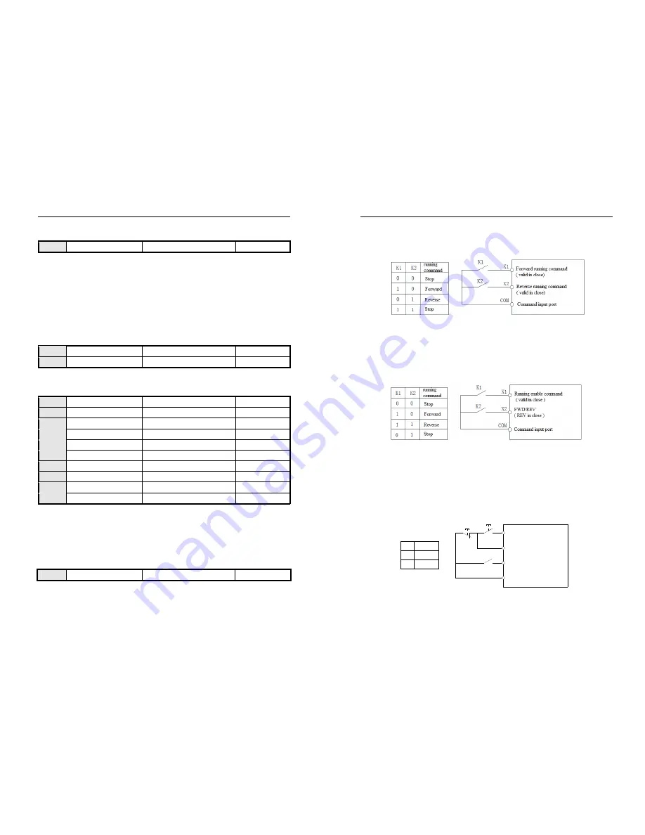
This parameter defines four different ways to control the operation of the drive via external terminals.
0: Two-wire control
AC300 Series Vector Control Inverter Manual
Function Parameter Specifications
81
The operation is in one direction. This mode is the most commonly used two-wire mode. The factory default is to
determine the forward and reverse running of the motor by the X1 (forward running) and X2 (reverse running) terminal
commands. As shown below:
0: Two-wire control 1 schematic
1: Two-wire control 2:
The operation is separated from the direction. The forward running terminal X1 (forward running) defined in this
mode is the operation enable terminal. The definition of the direction is determined by the state of the reverse running
terminal X2 (reverse running). As shown below:
1: Two-wire control 2 schematic
2: Three-wire control 1:
In this mode, the three-wire operation control terminal (Xi) is the stop operation terminal, and the running command
is generated by the forward rotation operation terminal X1 (forward rotation operation), and the direction is controlled by
the reverse rotation operation terminal X2 (reverse rotation operation). The three-wire operation control terminal (Xi) is
an effective input.
frequency inverter
K1
0
1
SB1
SB2
X1
Xi
X2
K1
COM
FWD/REV order(run while close)
stop order(stop while off)
run order(run while on)
common input port
FWD
REV
direction control
2: 3-line 1
2: Three-wire control 1 schematic


