6
S
etup
6
.
1
I
n general
T
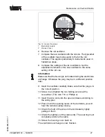
he numbers in brackets refer to the following illustrations
.
O
n the electronics module you will
fi
nd the following indicating
and adjustment elements
:
l
P
otentiometer for switching point adaptation
(
1
)
l
DIL
switch for mode adjustment
-
min
./
max
. (
2
)
l
S
imulation key
(
3
)
l
S
ignal lamp
(
6
)
6
.
2
A
djustment elements
Simulation
NAMUR IEC 60947-5-6
VB60N
4
5
6
1
2
3
F
ig
.
14
:
O
scillator with
NAMUR
output
1
P
otentiometer for switching point adaptation
2
DIL
switch for characteristics reversal
3
S
imulation key
4
G
round terminal
5
S
crewed terminals
6
C
ontrol lamp
Y
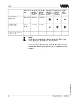
ou can adapt the switching point to the solid with the
potentiometer
.
T
he switching point is preset and covered by a
label
.
I
t must only be modi
fi
ed in special cases
.
B
y default
,
the potentiometer of
VEGAWAVE
63
is set to the
right stop
(
>
0
.
02
g
/
cm
³
or
0
.
0008
lbs
/
in
³
).
I
n case of very light
-
F
unction
/
C
on
fi
guration
S
witching point adaptation
(
1
)
20
VEGAWAVE
63
- -
NAMUR
S
etup
32259
-
EN
-
070117
Содержание VEGAWAVE 63
Страница 1: ...Operating Instructions VEGAWAVE 63 NAMUR ...
Страница 36: ...ø 34 mm 1 11 32 178 mm 7 1 64 Fig 21 Temperature adapter Supplement 36 VEGAWAVE 63 NAMUR 32259 EN 070117 ...
Страница 38: ...Supplement 38 VEGAWAVE 63 NAMUR 32259 EN 070117 ...
Страница 39: ...Supplement VEGAWAVE 63 NAMUR 39 32259 EN 070117 ...

