


24
5 Connecting to the bus system
VEGAPULS 65 • Foundation Fieldbus
36518-EN-140209
5.5 Wiring plan, double chamber housing Ex d ia
5
0
1
0
1
+
6 7 8
Bus
2
3
1
2
( )
(-)
4
1
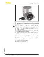
Fig. 17: Electronics compartment, double chamber housing Ex d ia
1 Internal connection to the connection compartment
2 Contact pins for the display and adjustment module or interface adapter
3 Simulation switch ("1" = mode for simulation release)
4 Internal connection to the plug connector for external display and adjust-
ment unit (optional)
+
Bus
2
1
2
( )
(-)
1
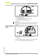
Fig. 18: Connection compartment, double chamber housing Ex d ia
1 Voltage supply, signal output
2 Ground terminal for connection of the cable screen
3
4
1
2
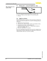
Fig. 19: Top view of the plug connector
1 Pin 1
2 Pin 2
3 Pin 3
4 Pin 4
Contact pin
Colour connection ca-
ble in the sensor
Terminal, electronics
module
Pin 1
Brown
5
Electronics compartment
Terminal compartment
Plug M12 x 1 for external
display and adjustment
unit


