


20
5 Connecting to the bus system
VEGAPULS 65 • Foundation Fieldbus
36518-EN-140209
5.2 Connecting
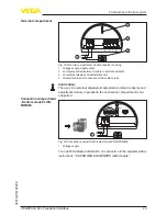
The voltage supply and signal output are connected via the spring-
loaded terminals in the housing.
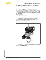
Connection to the display and adjustment module or to the interface
adapter is carried out via contact pins in the housing.
Information:
The terminal block is pluggable and can be removed from the
electronics. To do this, lift the terminal block with a small screwdriver
and pull it out. When reinserting the terminal block, you should hear it
snap in.
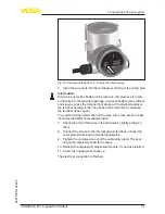
Proceed as follows:
1.
Unscrew the housing cover
2.
If a display and adjustment module is installed, remove it by turn
-
ing it slightly to the left.
3.
Loosen compression nut of the cable entry gland
4.
Remove approx. 10
cm (4
in) of the cable mantle, strip approx.
1
cm (0.4
in) of insulation from the ends of the individual wires
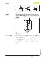
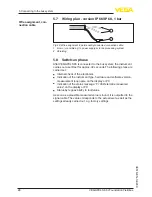
5.
Insert the cable into the sensor through the cable entry
Fig. 11: Connection steps 5 and 6 - Single chamber housing
Connection technology
Connection procedure


