background image

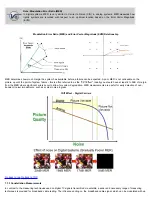
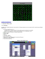
The diagram is an X/Y plot of the I (In-phase) and Q (Quadrature) axis components of the QAM signal and is particularly useful for

viewing impairments due to ingress and/or modulation problems present on the digital signal.

A symbol (essentially a waveform representing one or more bits) should ideally appear as a compact or clean dot in the center of

each symbol box. Decision boundaries exist within the constellation so that if the symbol falls within the boundary, the correct data

is received.

If due to noise or other interference, the symbol falls outside the boundary, the data is in error. Error detection and correction (e.g.

FEC) will attempt to the correct these errors, thus avoiding video impairments.

Observing the symbol's shape and location relative to their ideal positions allows you to draw some conclusions about the nature of

an impairment

Understanding the Constellation Diagram

Go back to top


Go back to TOC

The following impairments can be assessed visually:

Gain compression

 - Pulls the symbol clusters into the center while the middle ones are unaffected. Gain compression can result

from poor or bad amplifiers, IF equalizers and up/down converters.

Gain Compression

Broadband or system noise 

- Causes symbol clusters to enlarge, which increases the probability of errors. An error occurs when

the dot is pulled across a decision boundary.

Содержание VEPAL CX350S-D3.1

Страница 1: ...CX350s D3 1 e Manual D07 00 102P RevA01 Page 1 of 109 ...

Страница 2: ... 5 2 Utility Ports 5 0 Home Screen and Menu 5 1 Screen Layout 5 2 Screen Icons 6 0 Setup 6 1 Channel Tables and Locations 6 1 1 Channel Tables 6 1 2 Locations 6 1 3 Test Point Compensation 7 0 Test Applications 7 1 Single Channel Measurement 7 1 1 Analog Channel Measurements 7 1 2 Digital Channel Measurements 7 1 3 Constellation Measurements 7 2 Tilt Analysis 7 3 System Scan CX350s D3 1 e Manual D...

Страница 3: ...ator USG 7 7 Installation Check 7 8 Advanced Tools 7 8 1 Return Path Analysis 7 8 1 1 RP Level Measurements 7 8 1 2 RP Constellation Measurements 7 8 1 3 RP Measurement and Troubleshooting 7 8 2 Sweep Operations 7 8 3 Remote Operations 7 8 4 R Server 7 8 5 RP Balancing 7 8 6 TDR 7 8 6 1 Principles of Operation 7 8 6 2 Setup 7 8 6 3 Operation 7 8 6 4 TDR Profile 7 8 6 5 Typical Fault Displays 7 8 7...

Страница 4: ...nce of Fiber Connector Inspection 8 4 1 4 Fiber Connectors and Test Gear Vulnerabilities 8 4 1 5 About the DI 1000 Fiber Inspection Scope 8 4 1 6 Fiber Connector Inspection Setup 8 4 1 7 Capture Tab View 8 4 1 8 Captured Files Tab 8 4 2 Optical Power Meter OPM 8 4 2 1 Setting Pass Fail Limits 8 4 3 WiFi Spectrum Analyzer 8 4 4 Data Card 8 4 5 WiFi inSSIDer 8 4 6 OTDR Viewer 8 5 Web Browser 9 0 Uti...

Страница 5: ...nt 10 1 File Manager Working with Saved Results Profiles Images 11 0 Setup Main Menu 12 0 ReVeal Software 13 0 Warranty and Software 14 0 Product Specification 15 0 Certification and Declarations 16 0 About VeEX Go back to top CX350s D3 1 e Manual D07 00 102P RevA01 Page 5 of 109 ...

Страница 6: ...d a license solely to use the software as embedded in the device and the purchaser is prohibited from copying reverse engineering decompiling or disassembling the software This user manual is suitable for novice intermediate and experienced users and is intended to help you successfully use the features and capabilities of the VePAL CX350 test set It is assumed that you have basic computer experie...

Страница 7: ...gnal level meter capabilities and is equipped with enhanced spectrum forward and return path analysis functions The unit can be equipped with an optional DOCSIS 3 0 3 1 Cable Modem to validate DOCSIS and EuroDOCSIS based networks Equipped with an Upstream QAM Signal Generator USG the unit is able to perform advanced reverse path QAM analysis Go back to top Go back to TOC CX350s D3 1 e Manual D07 0...

Страница 8: ...ion however please observe all safety markings and instructions Do not operate the instrument in the presence of flammable gases or fumes or any other combustible environment VeEX Inc assumes no liability for the customer s failure to comply with safety precautions and requirements Go back to top Go back to TOC CX350s D3 1 e Manual D07 00 102P RevA01 Page 8 of 109 ...

Страница 9: ...cessed to prevent accidental power on Press the key for 3 5 seconds to turn the unit on To turn off the unit press the power key for at least 2 seconds If the unit does not respond holding the power key down by more than 10 seconds will force the unit to switch off Save key Saves test results in the unit s memory If the measurement is still running it will provide a snap shot the moment the key is...

Страница 10: ...se the arrow enter and escape keys to navigate The location of the cursor on the screen is indicated by a focus state The focus state varies depending on the function or section of the test set Please observe the following precautions Never use excessive pressure on the touch screen as this may damage its functionality Never use sharp objects such as a pen screwdriver etc as this may damage the su...

Страница 11: ...k to top Go back to TOC 4 5 Connectors and Panels The connector panel located at the top of the unit comprises the following test ports some are optional CX350s D3 1 e Manual D07 00 102P RevA01 Page 11 of 109 ...

Страница 12: ...5 10 100Base T port To access the Ethernet port remove the protective rubber cover on the right hand side of the unit to expose the connector Ethernet applications include IP connectivity testing Net Wiz testing WiFi Wiz testing Transfer measurement results and test profiles between the instrument and a computer using ReVeal CX software Upload download channel tables between the instrument and a c...

Страница 13: ...Go back to top Go back to TOC CX350s D3 1 e Manual D07 00 102P RevA01 Page 13 of 109 ...

Страница 14: ...odem Spectrum Analysis Installation Check TDR Advanced Tools to access more advanced features Return Path Analysis Sweep Operations Ethernet Tools Remote Operations R Server USG FEC RP Balancing HIP DS1 Tools Bottom Tbl Channel Table Select a channel table to test Loc Location Select Location threshold for particular test TP Test Point Select test point compensation Each of the menus listed above ...

Страница 15: ...navigation back to the main Home menu screen Close Closes screen and returns user to the previous screen QAM unlocked Indicates QAM lock has not been achieved on the digital carrier QAM lock Indicates QAM lock has been achieved on the digital carrier Note QAM lock is required to make Constellation measurements USG FEC On or Off Bluetooth Bluetooth detected Data GPS card Data GPS card detected Scre...

Страница 16: ...Go back to top Go back to TOC CX350s D3 1 e Manual D07 00 102P RevA01 Page 16 of 109 ...

Страница 17: ...les to perform measurements in Single Channel mode By default the unit is preloaded with several channel tables according to industry standard Annex A B and C systems Selecting a Channel Table Tap on next to Tbl to select a table from the drop down menu Channel Table Selection Go back to top Go back to TOC Editing or Creating New Channel Tables To create new channel tables or edit existing ones ta...

Страница 18: ...Channel Table Selection Channel Table Selection Select a table and press the Edit button Channel Table Editing CX350s D3 1 e Manual D07 00 102P RevA01 Page 18 of 109 ...

Страница 19: ...ocation settings are pre set measurement thresholds for analog and digital carriers By default the unit is pre loaded with Groundblock Set Top Box and Tap locators When performing a measurement one of these preset locations can be selected by tapping the check box Location Selection The measurement thresholds for the preset locations can be edited via the Setup icon and Main menu The manage functi...

Страница 20: ... preset test points can be selected by tapping the check box The test set stores 10 sets of TP compensation value by name Forward Comp applies to all Downstream related measurements such as Single Channel Installation Check and Cable Modem Downstream Levels Return Comp applies only to Cable Modem Upstream Transmit Levels TP Editor TP Selection CX350s D3 1 e Manual D07 00 102P RevA01 Page 20 of 109...

Страница 21: ...Go back to top Go back to TOC CX350s D3 1 e Manual D07 00 102P RevA01 Page 21 of 109 ...

Страница 22: ...to Noise C N ratios are indicated In digital mode the average power of the QAM channel is measured and MER and BER performance and other related parameters are displayed The channel to be measured can be entered by either tapping on the Channel box or the Frequency box to the right and use the pop up keypad to enter the channel number or frequency respectively After the first channel is entered us...

Страница 23: ...an bright scenes Using the sync pulses the carrier is at its peak power and it does not change from scene to scene therefore peak power has become the standard for analog video carrier level measurements The CX380S D3 1 measures the peak level for analog carrier Analog Carriers Peak Power Measurement CSO CTB The CX380S D3 1 measures the CSO CTB by taking the measurement at the programmed frequency...

Страница 24: ...gital Channel Measurements When testing a digital channel the unit first tries to lock onto the QAM signal Once the QAM signal is locked the unit starts displaying the digital measurement results as well as the constellation diagram Note QAM unlock If the unit is unable to lock onto the digital channel the following icon is displayed Always ensure QAM lock is achieved prior to making Constellation...

Страница 25: ... system failure this is often referred to as the Cliff Effect Ideally you should have at least 4 to 5dB of margin from the MER where significant errors occur to allow for system degradation MER measurements are useful for early detection of non transient noise impairments such as system noise Ingress Cliff Effect Digital Carriers Go back to top Go back to TOC 7 1 3 Constellation Measurements In co...

Страница 26: ...c The constellation display supports a zoom function For QAM64 and QAM256 modulation the constellation is split into 4 quadrants for simplified viewing The user can tap on any of the four quadrants to zoom into this selected quadrant Constellation Diagram Digital Carriers Note Bit Error Rate BER Bit Error Rate BER measures how often an error occurs in a given amount of data The more errors the mor...

Страница 27: ... data is in error Error detection and correction e g FEC will attempt to the correct these errors thus avoiding video impairments Observing the symbol s shape and location relative to their ideal positions allows you to draw some conclusions about the nature of an impairment Understanding the Constellation Diagram Go back to top Go back to TOC The following impairments can be assessed visually Gai...

Страница 28: ...e Coherent Interference Phase noise Also known as Phase jitter in a QAM signal it is caused by transponders in the transmission path or by the I Q modulator Phase jitter is a statistical quantity that affects the I and Q path equally Phase noise causes the symbol clusters to appear as arcs particularly those near the edges of the constellation Phase noise can also result from faulty headend up dow...

Страница 29: ...surement of modulation quality of the transmitted signal before forward error correction Error Vector Magnitude maximum symbol magnitude rms error magnitude X 100 Maximum AC maximum haystack amplitude change variation Carrier to Ingress Carrier to noise HUM in Phase jitter in degrees Symbol Rate Error in ppm Frequency Error in ppm deviation from nominal preset frequency Peak to Peak Frequency Resp...

Страница 30: ...dulated QAM carrier only as channel conditions change This process maximizes or greatly improves the Modulation Error Ratio MER in the forward or reverse path Impairment Graph Adaptive Equalizer Adaptive Equalizer Measurement The bar graph shows the performance of the Feed Forward Equalizer FFE and Decision Feedback Equalizer DFE circuitry The vertical axis displays the level in decibels dB while ...

Страница 31: ...to determine if there is any margin for system degradation To solve this problem the CX380 s adaptive equalizer can be turned off allowing a technician to easily identify sectionalize and locate these difficult linear type distortion problems Tap the function of Equalizer On Off to enable or disable the adaptive equalizer Tap Expert By further analyzing the behavior of the equalizer taps the follo...

Страница 32: ... then press the Enter key the Tilt measurement will measure the two most recently selected channels Typically the same analog and digital channels which have been recommended or defined for the Scan function should be used when performing Tilt measurements Often Tilt measurements are useful to identify excessive cable lengths at the customer premises that can cause high frequency roll off The CX38...

Страница 33: ...ormed for each analog channel Video Power Level in dBmV dBuV Audio1 Power Level in dBmV dBuV V A1 Ratio in dB System Scan Go back to top Go back to TOC Digital Scan The following measurements will be performed for each digital channel QAM Power Level in dBmV Once the test is completed or stopped by the user a marker is available and can be placed on any of the measured channels The measurements of...

Страница 34: ... intermediate frequency The frequency of the VCO is controlled by a repeating ramp generator whose voltage also drives the horizontal axis of the display As the frequency of the VCO changes the intermediate frequency sweeps through the resolution bandwidth filter IF filter which is fixed in frequency 3 A detector then measures the power level of the signal passing through the IF filter producing a...

Страница 35: ...lter that may also be used to average the reading These filters must have time to respond otherwise signals will be missed and the measurements rendered useless Nevertheless it is still essential to keep the scan rate as high as is reasonably feasible to ensure that measurements are made as quickly as possible Selectable sweep times are 30 50 100 150 200 250 300 and 1000ms For a larger span due to...

Страница 36: ...of the display increase of the attenuation becomes necessary until the peak of the signal is about 10dB below the top of the spectrum display The full 60dB dynamic range upper and lower limits are shown as purple lines horizontally on screen Note To optimize the Spectrum Analyzer for Noise Floor Detection take the following steps 1 Go to Setup Main Menu 2 Set the SA Pre AMP setting to AUTO Thereaf...

Страница 37: ...OCSIS RF Specification recommends that the average power of a downstream digitally modulated carrier be set 6dB to 10dB below what the amplitude of an analog TV channel on the same frequency would be Before measuring or setting the amplitude of a digitally modulated carrier first measure the amplitude of the cable network s analog TV channels Digital Carrier amplitude measurement On a digital carr...

Страница 38: ...ference that is coupled into the forward or return path cable plant via an external source and can be broadly categorized as follows Narrow band ingress The predominant coupling mechanism for ingress noise is a poorly shielded drop coaxial cable that acts more like an antenna than a drop cable AM modulated carriers amateur band and maritime radio transmission generate unwanted signal frequencies a...

Страница 39: ...ier effect which produces potentially harmful 2nd and 3rd order Intermodulation Distortion IMD products or beats These beats will occur every 6 7 or 8MHz in the reverse path depending on the channel plan used Although the magnitude of these beats is small they increase at a node when several reverse paths are combined Go back to top Go back to TOC 7 5 Cable Modem Overview Historically CATV was a u...

Страница 40: ...n DOCSIS 3 1 cable modem as an option The built in cable modem is able to range register and connect with the headend CMTS to obtain the necessary parameters and a valid IP address on the network Launch the Cable Modem application to access the Setup screen Cable Modem Setup ...

Страница 41: ...the actual cable modem Always On terminate mode and also enables the Cable Modem to remain online when you exit from the Cable Modem This allows you have online connectivity while using other features such as Remote View and V300 R Server access Once these settings are completed press Connect Once connect is pressed the test set will go directly to the result page Each step of the connection proce...

Страница 42: ...SP message for frequency power and timing settings 6 CMTS periodically sends keep alive messages to verify link continuity between itself and all CM units in the same domain When a CM receives its first keep alive message it reverts to a fine power ranging 7 CM now forwards a bandwidth request to the CMTS which in turn forwards a grant to the CM permitting it to forward upstream information in all...

Страница 43: ...sfer Protocol TFTP server Defined by RFC1350 for the purpose of registering and downloading CM configuration files for individual customer service These configurations could include Quality of Service QoS parameters Baseline Privacy Implementation BPI operating frequency assignments the number of host devices etc Go back to top Go back to TOC 7 5 2 Cable Modem Results DOCSIS 3 0 Ranging tab Provid...

Страница 44: ...k to TOC Link tab Provides information about the packets received the downstream signal frequency modulation level MER and about the upstream signal frequency level modulation Cable Modem Link Results Downstream Cable Modem Link Results Upstream ...

Страница 45: ...TP tab The IP functions are similar to the ones described in IP Tools ARPWiz is not supported on the Cable Modem interface Go back to top Go back to TOC VeTest VeTest is a throughput test to an actual customer speed test server site In the Web FTP tab select Mode as VeTest Then make appropriate selections for Provider and VeTest Server If you cannot find the selections you are looking for you can ...

Страница 46: ... modem In the Setup screen select Pass Through for the Test Mode and press Connect Once the Cable Modem goes online connect a PC to the meter s 10 100 1000T RJ45 port at the top of the unit Traffic will pass through the meter which functions like an actual cable modem Cable Modem Pass Through ...

Страница 47: ... for DOCSIS 3 1 OFDM Systems For testing with DOCSIS 3 1 systems follow these steps 1 For a system that contains both Single Carrier QAM SC QAM and OFDM channels enter the primary SC QAM DOCSIS Channel number and press Connect to go online Ranging tab Online Status in D3 1 Mode ...

Страница 48: ...Graphs tab Online Status in D3 1 Mode D3 1 OFDM Tab Results OFDM Tab measurements Level reports Average Maximum and Minimum for the OFDM PLC Frequency Primary OFDM PLC Frequency ...

Страница 49: ...l Generator with FEC Correction USG FEC Overview The Upstream Signal Generator USG function generates a signal for upstream or return path testing The USG FEC option supports CW CW 2 tone QPSK QAM 16 Annex A QAM 64 Annex B QAM 128 Annex A and QAM 256 Annex B signal generation QAM 16 STD Annex A QAM 64 STD Annex A and QAM 128 STD Annex A are with ITU standard interleave i j settings The frequency i...

Страница 50: ...nd QAM Analyzer Functions Go back to top Go back to TOC 7 7 Installation Check Overview This function performs measurements on user pre defined channels Up to 16 analog channels and or 16 digital channels can be pre programmed OFDM the Japanese standard channels can also be programmed requires the OFDM option to be enabled Each channel table has its own installation check settings The user can mod...

Страница 51: ...ummary screen The selected channels for the installation check test need to be active on the selected channel table The installation check derives the pass and fail criteria by comparing the measured values to pre selected thresholds locations If no parameter has been selected on the active location a warning message will be displayed Go back to top Go back to TOC Analog Channels The following mea...

Страница 52: ...e Return Path Analysis Sweep Operations MPEG Operations Remote Operation R Server TPS Control More RP Balancing HIP Headend Check FCC POP Advanced Tools Menu Go back to top Go back to TOC 7 8 1 Return Path Analysis Overview The Return Path refers to the path of the signals sent by cable modems at home to the CMTS located at the headend Cable Modems on the same co axial cable are time sharing the b...

Страница 53: ...W Bandwidth and MOD Modulation to match far end USG unit 3 Press Start Look for the QAM lock logo to transition to green and for measurements to begin Go back to top Go back to TOC 7 8 2 Sweep Operations Overview Sweep is used to identify improper balance of amplifiers tilts or suck outs Tilt and Suck Out Starting from a drop point nearest to the signal source for example a Headend office a Sweep ...

Страница 54: ... channels to obtain the frequency response of the HFC networks Forward Path Sweep This function verifies the frequency response and proper operation of the amplifiers It is a one person operation with Internet connection and requires Remote View and Sweep options on CX380 In Band Sweep CX380S D3 1 also supports In Band Sweep for Return Path and Forward Path For In Band Sweep no separate connection...

Страница 55: ...create bogus alarms in other areas Until the continuity problems are resolved it will be very hard to determine if there are other problems in the stream The PAT Program Associate Table is on PID 0x00 This is the first PID a decoder looks at the MPEG Base PID The CX380S D3 1 can be optioned to perform MPEG analysis of a digital carrier that contains MPEG programs The following functions are availa...

Страница 56: ...thout a good strong signal analysis of the MPEG stream may not yield any useful information Check FEC counters and use Constellation diagram to identify problems Disable enable Equalizer to check QAM decoder performance group delay and frequency response ...

Страница 57: ...Go back to top Go back to TOC 7 8 4 Remote Operations ...

Страница 58: ...figuring the unit as a Responder unit This mode is used for Return Path Sweep and Remote View with a far end CX3XX configured as a Controller It is possible to conduct remote operations between CX380S D3 1 field unit to CX180R system and from CX380S D3 1 to another CX380 For operations between CX380S D3 1 field unit and CX180R The communication between these two units is done via Internet connecti...

Страница 59: ...Setup menu Enter the USG test parameters then press Start Tabs are available on the USG home screen to allow quick access of Spectrum Analysis mode and Return Path Analysis mode To conduct Spectrum Analysis 1 From the Home menu enter Spectrum Analysis 2 Port number for spectrum analysis can be changed from Port 1 to Port 10 3 Tap USG FEC to enter USG FEC setup page 4 Spectrum analysis bandwidth is...

Страница 60: ... Remote View menu and press Disconnect To conduct Spectrum Analysis 1 From the Home menu enter Spectrum Analysis Spectrum analysis can be from 5 to 1000MHz The sample shown is the QAM signal generated by the CX380 Controller unit and measured by the CX380 Responder unit Live spectrum traces are sent from the CX380 Responder and displayed by the CX380 Controller in real time via Internet connection...

Страница 61: ...0S D3 1 1 to control external TPS Test Point Selector or Matrix Switch in order to access a node through the cascade of TPSs It also allows re use of already installed TPS matrix switches and enhances path test capability by replacing the out of date test unit Please note that an USB to Serial converter is needed and will be provided with this option Go back to top Go back to TOC 7 8 7 RP Balancin...

Страница 62: ...ates Digital POP tests The optional FCC POP Feature consists of various Auto Tests System Tests Analog Levels Video Level Audio Level 1 2 Video Audio Ratio 1 2 Max Adjacent Channel Digital Levels Level MER Pre BER Post BER Adjacent Channel Digital POP Level MER Pre BER Post BER Frequency Response EQ Stress Estimated Noise Margin ENM Error Vector Magnitude EVM Group Delay Phase Jitter Analog Distor...

Страница 63: ...l available Upstream Channel Descriptors provided by the CMTS from a specific downstream DOCSIS channel For a selected UCD captures and decodes burst Cable Modem signals Assesses QAM health for the UCD by measuring Upstream MER burst constellations and codeword error rates Identifies associated Cable Modem MAC Addresses which helps identify rogue Cable Modems Follow these steps to run a QAM Wiz te...

Страница 64: ...2 Input the CMTS DOCSIS Channel number and press Apply QAM Wiz Channel Input 3 Select the desired UCD and press Analyze QAM Wiz UCD ...

Страница 65: ...ay take up to one minute to display results Typically within 30 seconds various Upstream measurements will be displayed Press the MAC List to view associated Cable Modem MAC Addresses MAC Addresses Go back to top Go back to TOC ...

Страница 66: ...t configuration IP Address Select from Static or DHCP Static If Static is selected the user will manually enter the IP address parameters local IP Gateway IP and DNS server IP DHCP If DHCP is selected the unit will obtain IP address parameters from the DHCP server Gateway and DNS Enable or Disable Enabled If enabled enter the IPv4 address of the Gateway and DNS server in Static mode or use the IP ...

Страница 67: ... with any IP tests If the connection fails go back to the setup screen to verify that the parameters are entered correctly Verify that the Ethernet cable is properly connected on the management port DHCP PASS indicates that an IP address has successfully been assigned IP PASS indicates that the IP address assigned has been verified to be unique in the network Gateway PASS indicates that the gatewa...

Страница 68: ... pings per second Time Out Time to Live TTL in milliseconds Use the alphanumeric keypad to enter the maximum time allowed in ms up to 99999ms between an ICMP ping and echo response Once the parameters are configured press Start to begin the test Ping Setup Go back to top Go back to TOC Ping Results Pressing Ping will take you to the Result tab and start the Ping test Destination Indicates the dest...

Страница 69: ...e file or create a new test Destination Enter the IP address or URL of the network device to be detected Time Out Enter the maximum time allowed between an ICMP echo and response at each hop Max Hop Enter the maximum number of network devices the packet is allowed to transit Once the parameters are configured press Start to begin the test Trace Route Setup Go back to top Go back to TOC Trace Route...

Страница 70: ...Trace Route Result Go back to top Go back to TOC CX350s D3 1 e Manual D07 00 102P RevA01 Page 65 of 109 ...

Страница 71: ...esired IP range using the numeric keypad Select the test by placing a check mark in the corresponding box of any of the following ARP Ping Net Wiz Setup Go back to top Go back to TOC 8 2 2 Net Wiz Results Summary indicates the test status and reports TX RX Frames Total number of TX transmitted and RX received frames RX Errors Received frames in error Speed Advert Speed advertised Duplex Advert Dup...

Страница 72: ...vices found Number of devices Routers Servers Hosts Net Wiz Results Devices Global Detail displays the Attribute MAC and IP Addresses and Ping test results of each device discovered Net Wiz Results Devices Detail Go back to top Go back to TOC CX350s D3 1 e Manual D07 00 102P RevA01 Page 67 of 109 ...

Страница 73: ...ort Signal Strength IP Connection and Ping Test Go back to top Go back to TOC 8 3 1 WiFi Procedure Plug the WiFi adaptor into the USB port Allow at least 30 45 seconds for the unit to detect the wireless adaptor and for the software driver to load Note Products support USB wireless adaptors supplied by VeEX only and have the necessary software driver built into the test set Tap on the Scan tab onc...

Страница 74: ...ght hand side bar Tap on Edit Settings or Connect AP to change the Encryption Type and enter the WiFi Key Encryption Type Supported encryption types include WEP WPA and WPA2 Key Security phrase or password necessary to access SSID and network Tap the Key field to enter the AP password on the pop up keypad ASCII formatting supported The password phrase can be hidden Global Settings Show Password Ye...

Страница 75: ...nel connected to Encryption Encryption type Mode Signal Radio signal level dBm Link quality score Max data rate 802 11 protocols supported WiFi Wiz Connection Status After a successful connection to the Access Point press Connect IP to obtain an IP address and access the additional IP tests like Ping Trace Route etc WiFi Wiz Connect IP CX350s D3 1 e Manual D07 00 102P RevA01 Page 70 of 109 ...

Страница 76: ...Go back to top Go back to TOC CX350s D3 1 e Manual D07 00 102P RevA01 Page 71 of 109 ...

Страница 77: ... related standards and general industry practices recommend the following Markings on the core or damage to the cladding close to the core are unacceptable Slight scratches and small pits on the cladding away from the core are however acceptable Cracks are not permitted in neither core nor cladding Equipped with 400x magnification the VeEX Fiber Scope Inspector is well suited for general installat...

Страница 78: ...ernal motors makes a better choice for field applications No training necessary yet get it right every time Smaller scope size Report generation html and PDF The test set detects when the image has reached optimal focus level automatically freezes the picture captures the image and runs the IEC 61300 3 35 analysis No need to move hands or press any buttons movement and vibration are common causes ...

Страница 79: ...ace allowing users to align and focus Fiber Scope Capture tab Important The soft buttons in the action bar right side of the screen do not indicate the current state or setting they indicate the action that would take place if pressed For example if user taps on the Analysis OFF button the analysis function is turned OFF and the button toggles to show Analysis ON These soft buttons should be inter...

Страница 80: ...b This section of the user interface lists all the connectors end face images that have been captured with the fiber inspection microscope Users can and Before and After identifiers or remainders when comparing images before or after cleaning or polishing Clear All Deletes all the image files in the Captured Files list Delete Deletes any selected files from the Captured Files list Use the check bo...

Страница 81: ... navigate select and load any other file Show Hide Overlay Enables or disables the mask anomalies identification and analysis Finer From To User customizable labels to identify the fiber under test Save Report Generates a full report including a table with measurements and images Use the Utilities Files function to View the report export to PDF format and copy to USB CX350s D3 1 e Manual D07 00 10...

Страница 82: ...defects and scratches count by sizes and position used for the evaluation of the Pass Fail criteria according to the IEC 61300 3 35 standard Go back to top Go back to TOC CX350s D3 1 e Manual D07 00 102P RevA01 Page 77 of 109 ...

Страница 83: ...attenuated by the fiber The results are presented in dB Loss meter requires to be referenced calibrated to the Laser Source output You must connect the LS to the OPM dongle using a short patch cord and tap on the Reference button to record the 0dB point Then that LS can be connected to the far end of the fiber to measure the loss Hold Freezes the last power or loss reading on the screen Save Recor...

Страница 84: ...ctrum analyzer on a USB dongle that displays all RF activity in the WiFi bands e g s wireless networks cordless phones microwave ovens Bluetooth devices etc It offers the following capabilities Helps determine the best available WLAN channels quickly for optimal performance Helps to visualize and locate RF signals in the 2 4GHz and 5GHz spectrums Discover and remedy competing access points Optimiz...

Страница 85: ...across the entire spectrum Spectral view Historical view of wireless spectrum use at a point in time WiFi SA Planar View Planar View Traditional Spectrum Analyzer view with Max Average and Current results Displays RF activity in real time and tracks average and max values over a given period WiFi SA Topographic View CX350s D3 1 e Manual D07 00 102P RevA01 Page 80 of 109 ...

Страница 86: ...ndication of the typical local network conditions WiFi SA Spectral View Spectral View Waterfall type view across the whole band graphs amplitude levels over time Uses color to pick out the relative signal strength at each point in time Great tool for troubleshooting intermittent problems since it highlights devices that are perhaps emitting only short bursts of noise For example discover microwave...

Страница 87: ...idebar and click the pattern in the Topographic view to identify a device WiFi SA Inspector Inspector The Inspector button setup allows the user to measure the frequency of the RF activity or interference of interest When selected a prompt and result box appears WiFi SA Inspector Result CX350s D3 1 e Manual D07 00 102P RevA01 Page 82 of 109 ...

Страница 88: ...ect frequency band for testing Go back to top Go back to TOC 8 4 4 Data Card To establish an IP connection using a data card please make sure that the data card is connected on the USB port Note that only datacards provided by VeEX are supported and have the driver necessary for connection The Data Card icon as shown below will appear at the bottom of the screen Data Card Setup CX350s D3 1 e Manua...

Страница 89: ...ation parameters then press Connect Now that a connection has been established The D for Data in the icon turns green The connection details are displayed in the IP Tools Status tab shown below It will automatically reconnect if the test set is powered off on and you are in a good reception area It will automatically reconnect if you enter a bad cell area and return to a good one CX350s D3 1 e Man...

Страница 90: ... access points AP detected in the 2 4 GHz and 5GHz bands The following information is displayed for each AP SSID name of the AP BSSID MAC address of the AP 802 11 protocol version supported by the AP Max data rate supported by the AP AP s radio channel number Lock symbol indicates if security is set on the AP WEP WPA or WPA2 When the AP is unsecured no lock symbol is displayed Signal strength of t...

Страница 91: ...gate the graph and get additional information for the access points Detailed information for each Access Point includes SSID name of the AP AP s radio Channel number Signal strength dBm Number of co channel Number of APs using the same radio channel Number of Overlapping APs Number of APs using channels whose frequency band overlaps with the AP CX350s D3 1 e Manual D07 00 102P RevA01 Page 86 of 10...

Страница 92: ... TX300S OTDR RXT 4100 OTDR FX300 OTDR or SunLite OTDR test sets It can also be used to control the wireless OPX BOX OTDR via Bluetooth or USB connection offering full featured OTDR functionality Please refer to the OTDR manual for further details about its operation Go back to top Go back to TOC CX350s D3 1 e Manual D07 00 102P RevA01 Page 87 of 109 ...

Страница 93: ...uilt in web browser uses the management port IP connection An active IP connection can be established either through Ethernet WiFi or datacard ports The web browser defaults to VeEX s website Use the Web browser s navigation bar to enter the name of the website you wish to reach Web Browser Go back to top Go back to TOC CX350s D3 1 e Manual D07 00 102P RevA01 Page 88 of 109 ...

Страница 94: ...ings for the global parameters of the test set or platform system settings Settings Menu Go back to top Go back to TOC 9 1 1 About This section provides information about the software version serial number and MAC address of the management port of the unit as well as a list of software licenses optional test features currently loaded in the test set Utility Settings About CX350s D3 1 e Manual D07 ...

Страница 95: ... to start the calibration feature and repeat the procedure Go back to top Go back to TOC 9 1 3 Bluetooth VeEX products support a micro USB Bluetooth adaptor offering wireless connectivity up to 10 meters 30 feet Ultra compact and portable the adaptor provides an untethered connection between the tester and other Bluetooth compatible devices such as a Notebook PC or cell phone so the user can trans...

Страница 96: ...n external USB hub to connect additional devices Once detected a Bluetooth icon is displayed on screen Devices The test platform will automatically detect the Bluetooth adaptor once plugged into the USB port Details of the Bluetooth adaptor will be displayed including the MAC address of the device and the last 4 digits of the serial of the V300 test set The last 4 digits of the V300 series test se...

Страница 97: ...e during Scanning and Pairing operation Press Pair BT to begin the pairing process During the pairing operation you will be prompted to enter a code on the peripheral device PC or Mobile Phone in order to pair successfully Enter the last 4 digits of the V300 serial number as shown in the Connection tab Once paired click the Services button at the bottom of the screen to check the service attribute...

Страница 98: ...onnection Page 2 Go back to top Go back to TOC 9 1 4 Power This section provides information about current power source and information about the battery gauge Tap on the battery icon on the top bar to bring battery charge and estimated autonomy information Utility Settings Battery Power CX350s D3 1 e Manual D07 00 102P RevA01 Page 93 of 109 ...

Страница 99: ...is function helps improve the battery autonomy and preserve LCD life To enable the timer check Turn off backlight if device is not used for and with the drop down menu adjust the duration of the idle time before the backlight is turned off Once the timer is active and the backlight turned off any action on the test set touch screen keypad will turn on the backlight again Backlight Battery Power Ba...

Страница 100: ... or Metric meter Audible Alarm When enabled the test set s buzzer will sound beep when alarms and errors are being detected Show Password Hides unhides username and password information associated with FTP and related IP functions User Interface The USA user interface version presents SONET DSn application oriented menus while the International setting is more open to all settings Utility Settings...

Страница 101: ...e Setting Save Screen Settings Save Screen tab Helps control the behavior of the Lock key on the keypad The Lock key can be set to do the following Lock Unlock the unit s screen to prevent accidental interruption during a long term test Save Screen Shots The following configurations can also be done The compression level of the screen picture Maximum number of screenshots that can be saved Each ti...

Страница 102: ...s There are different ways to control or access the test set and the information it contains from a local LAN or remote WAN connected PC ReVeal PC software VNC Client Go back to top Go back to TOC ReVeal CX300 This VeEX application allows users to connect to the test set using the platform s IP address ReVeal intuitive user interface offers the following functions CX350s D3 1 e Manual D07 00 102P ...

Страница 103: ...emote VNC clients to view and control the user interface via mouse Regular User Password Allows remote VNC users guests to view what s currently on the test set screen but no interactions with the GUI are allowed Although the test set VNC services allows multiple users to be connected simultaneously it is a screen mirroring service so all users would be seeing and interacting with the same GUI Suc...

Страница 104: ...VNC Viewer Password Prompt Go back to 9 1 8 Remote Access Go back to top Go back to TOC CX350s D3 1 e Manual D07 00 102P RevA01 Page 99 of 109 ...

Страница 105: ...es Tap on any column header to sort by that specific parameter Tap again to change the sorting order The U L button lock and unlock files to prevent accidental deletion PDF button converts all selected files to PDF format Requires FAT32 USB Memory stick Backup and Restore USB Memory stick To USB copies all selected files to stick From USB restores all files from the stick BT Bluetooth File Transfe...

Страница 106: ...tivate Filters Use the stylus to tap on the Y icon Check mark the desired attributes Filters parameters can be combined Reset Filters Press the Show All button Sorting Tap on a header to sort by that field s type in ascending or descending order Makes finding desired test Results or Reports even easier Go back to top Go back to TOC CX350s D3 1 e Manual D07 00 102P RevA01 Page 101 of 109 ...

Страница 107: ...ccidentally erasing of pre stored channel tables Sweep table RP To edit and create return path sweep tables CM Always on Choose if the Cable Modem software should be pre loaded after first powered on TDR Cable Type Pre select the cable type to be tested for the TDR function You can setup the known Vp and Impedance values as well Spectrum Start Mode Select the default mode for Spectrum Analysis OFD...

Страница 108: ...r more information on using the ReVeal CX300 software refer to the ReVeal CX300 PC Software for CX300 series User Manual at www veexinc com Go back to top Go back to TOC CX350s D3 1 e Manual D07 00 102P RevA01 Page 103 of 109 ...

Страница 109: ...e customer along with proof of purchase within thirty 30 days of the request by the customer freight prepaid Additionally during the warranty period VeEX Inc will provide without charge to the customer all fixes patches and enhancements to the purchased software firmware and software options VeEX Inc does not warrant that all software or firmware defects will be corrected New enhancements attached...

Страница 110: ...e Product Specifications The most recent product specifications can be downloaded from the VeEX website For the most recent version www veexinc com Go back to top Go back to TOC CX350s D3 1 e Manual D07 00 102P RevA01 Page 105 of 109 ...

Страница 111: ...ropean Free Trade Association EFTA EN61010 1 For a copy of the CE Declaration of Conformity relating to VeEX products please contact VeEX customer service What is RoHS RoHS is the acronym for Restriction of Hazardous Substances Also known as Directive 2002 95 EC it originated in the European Union and restricts the use of specific hazardous materials found in electrical and electronic products All...

Страница 112: ...e distribution channel provides uncompromised product support Visit us online at www veexinc com for latest updates and additional documentation VeEX Incorporated 2827 Lakeview Court Fremont CA 94538 USA Phone 1 510 651 0500 Fax 1 510 651 0505 Customer Care Phone 1 510 651 0505 Email customercare veexinc com Go back to top Go back to TOC CX350s D3 1 e Manual D07 00 102P RevA01 Page 107 of 109 ...

Страница 113: ...pliance Portable RoHS analyzers also known as X ray fluorescence or XRF metal analyzers are used for screening and verification of RoHS compliance Which companies are affected by the RoHS Directive Any business that sells applicable electronic products sub assemblies or components directly to EU countries or sells to resellers distributors or integrators that in turn sell products to EU countries ...

Страница 114: ...ents 10 Automatic dispensers VeEX position and product status Our quality and environmental policy is to limit and progressively eliminate the use of hazardous substances and chemicals in the design and manufacture of our products VeEX products are classified as Monitoring and Control Instruments under Article 2 Section 1 Category 9 of the WEEE 2002 96 EC Directive and are therefore exempt to the ...

Отзывы: