33
34
Summary
25
50
75
100
1
25
150
175
0
10
20
3 0
40
5 0
6 0
7 0
8 0
9 0
1 0 0
2
0
0
2
25
2
5
0
275
3
00
0
Safe
Operating
Region
D
u
ty C
y
c
le
(P
E
R
C
E
N
T
A
G
E
)
Welding Current(AMPS)
2.4 Packaged items
Plasma
40D
◆
Plasma torch 4m PT-31
◆
300A earth clamp with 3m cable
◆
1.8m Gas hose 8x13.5
◆
Air Regulator
◆
Operating manual
Plasma 60D
◆
Plasma torch 4m AG-60
◆
300A earth clamp with 3m cable
◆
1.8m Gas hose 8x13.5
◆
Air Regulator
◆
Operating manual
Plasma 70PD
◆
Plasma torch 4m AG-60
◆
300A earth clamp with 3m cable
◆
1.8m Gas hose 8x13.5
◆
Air Regulator
◆
Operating manual
Plasma 100PD
◆
Plasma torch 4m P
-
80A
◆
300A earth clamp with 3m cable
◆
1.8m Gas hose 8x13.5
◆
Air Regulator
◆
Operating manual
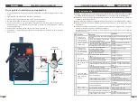
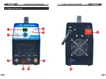
3.1 Layout for the panel
Operation
PLASMA
CUTTING SERIES EQUIPMENT
PLASMA
CUTTING SERIES EQUIPMENT
6
8
7
5
2
3
1
4
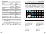
2.3
Duty Cycle
The rated duty cycle of a Welding Power Source is a statement of the time it may be
operated at its rated welding current output without exceeding the temperature limits of the
insulation of the component parts. To explain the 10 minute duty cycle period the following
example is used. Suppose a Welding Power Source is designed to operate at a 60% duty
cycle, 100 amperes at 120 volts. This means that it has been designed and built to provide the
rated amperage (100A) for 4 minutes, i.e. arc welding time, out of every 10 minute period (60%
of 10 minutes is 4 minutes). During the other 6 minutes of the 10 minute period the Welding
Power Source must idle and be allowed to cool.


