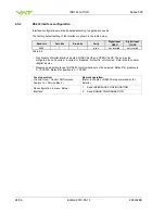


INSTALLATION
Series 590
18/56
Edition 2013-05-13
298292EB
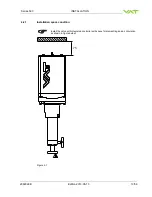
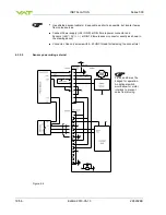
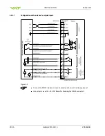
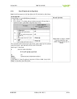
Use shielded sensor cable(s). Keep cable as short as possible, but locate it away
from noise sources.
Connect Power supply (+24 / GND) at DB
–9 male power connector and
Sensors (+24V / 0V / + / -) at DB
–15 female sensor connector exactly as shown in
the drawing above!
Connector: Use only screws with 4
–40 UNC thread for fastening the connectors!
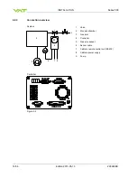
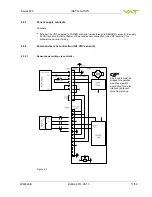
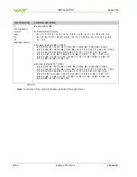
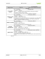
4.3.2.2
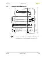
Sensor power wiring external
Figure 4-4
Pins 4 and 8 must be
bridged for operation.
An optional switch
would allow for motor
interlock to prevent
valve from moving.


