


2920 Float & Tape Transmitter
5 Display and Configuration Interface
52
Installation and Operations Manual
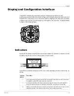
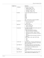
The right status indicators display input and output status, and an indicator that shows the unit
is functioning normally.
The top indicator displays digital input status, as a single hexadecimal digit, 0 to F. Bit 0
indicates digital input 1. Bit 1 indicates digital input 2. Bit 2 indicates digital input 3. Bit 3
indicates digital input 4. A value of 0 indicates that no digital inputs are active. A value of F
indicates that all for digital input are active.
The middle indicator displays the output relay status as a single hexadecimal digit, 0 to F. Bit 0
indicates digital relay 1. Bit 1 indicates digital relay 2. Bit 2 indicates digital relay 3. Bit 3
indicates digital relay 4. A value of 0 indicates that no relays are active. A value of F indicates
that all for relays are active.
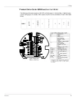
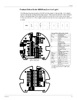
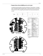
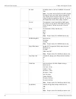
The following table shows the activity of the Digital Input or Output Relay for each
hexadecimal digit.
The lower indicator is a bar that sequences about every 1/2 second to indicate the transmitter
CPU is running. This indicator is commonly referred to as the heartbeat.
Hex Indicator Input 1/
Relay 1
Input 2/
Relay 2
Input 3/
Relay 3
Input 4/
Relay 4
0
Inactive
Inactive
Inactive
Inactive
1
Active
Inactive
Inactive
Inactive
2
Inactive
Active
Inactive
Inactive
3
Active
Active
Inactive
Inactive
4
Inactive
Inactive
Active
Inactive
5
Active
Inactive
Active
Inactive
6
Inactive
Active
Active
Inactive
7
Active
Active
Active
Inactive
8
Inactive
Inactive
Inactive
Active
9
Active
Inactive
Inactive
Active
A
Inactive
Active
Inactive
Active
B
Active
Active
Inactive
Active
C
Inactive
Inactive
Active
Active
D
Active
Inactive
Active
Inactive
E
Inactive
Active
Active
Active
F
Active
Active
Active
Active
Содержание 2920
Страница 2: ......
Страница 16: ...2920 Float Tape Transmitter 1 Introduction 6 Installation and Operations Manual...
Страница 114: ...2920 Float Tape Transmitter 6 Bi Phase Mark 104 Installation and Operations Manual...
Страница 120: ...2920 Float Tape Transmitter 7 MODBUS 110 Installation and Operations Manual...
Страница 126: ...2920 Float Tape Transmitter 9 L J TankWay 116 Installation and Operations Manual...
Страница 138: ...2920 Float Tape Transmitter 11 Configuration Calibration Level Limits and Outputs 128 Installation and Operations Manual...
Страница 148: ...2920 Float Tape Transmitter 12 Maintenance and Troubleshooting 138 Installation and Operations Manual...
Страница 158: ...2920 Float Tape Transmitter 14 Ordering Information 148 Installation and Operations Manual...
Страница 178: ...2920 Float Tape Transmitter MODBUSAppendix A MODBUS Implementation 168 Installation and Operations Manual...
Страница 193: ......