


2920 Float & Tape Transmitter
4 Wiring
22
Installation and Operations Manual
Discrete Inputs
As standard, the 2920 FTT contains 2 discrete inputs for connection to ancillary devices such
as limit switches and float switches. The 2920 FTT then provides an Open/Closed signal to the
host system. All wiring must be connected to the appropriate terminals DI1, DI2, and DICOM
in the junction box supplied with the 2920 FTT.
When the AC Power option is installed, an additional 2 discrete inputs are available. Review
the terminal assignment tables to determine the terminal locations of DI3 and DICOM for the
appropriate order code. The terminal for DI4 is located on the terminal board in the Expansion
Junction box.
Input Power
Warning
Never apply A/C power to terminals B+ and B-. Damage to the main board will
result.
Warning
Verify the positions of switches SW1 and SW2 on the A/C power board before
applying A/C power to the transmitter. Damage to the transmitter may result. See
“Connector and Switch Locations: AC Power Supply Circuit Board” on page 47.
The standard 2920 FTT uses 20-65 V DC power, supplied through the main communications
board. With an optional AC power PCB, the 2920 FTT can also be supplied with 40-65 VAC, 100-
120 VAC, or 220 - 240 VAC at 50/60 Hz.
DC power is connected to the B+ and B- terminals on the terminal board in the Main Junction
box. Review the terminal assignment tables to determine the terminal locations of LINE (AC
Line) and NEUT (AC Neutral) for the appropriate order code.
Note
Before connecting power wires to the 2920 FTT, ensure that power is switched off
and the instrument is correctly grounded.
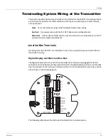
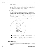
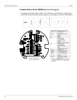
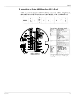
Terminals T1 through T8 are dependent on order codes. See the wiring diagrams for terminal
assignments based on order codes.
Note
Each junction box includes Earth Ground terminal located on the terminal circuit
board. Ensure the external ground is connected.
Содержание 2920
Страница 2: ......
Страница 16: ...2920 Float Tape Transmitter 1 Introduction 6 Installation and Operations Manual...
Страница 114: ...2920 Float Tape Transmitter 6 Bi Phase Mark 104 Installation and Operations Manual...
Страница 120: ...2920 Float Tape Transmitter 7 MODBUS 110 Installation and Operations Manual...
Страница 126: ...2920 Float Tape Transmitter 9 L J TankWay 116 Installation and Operations Manual...
Страница 138: ...2920 Float Tape Transmitter 11 Configuration Calibration Level Limits and Outputs 128 Installation and Operations Manual...
Страница 148: ...2920 Float Tape Transmitter 12 Maintenance and Troubleshooting 138 Installation and Operations Manual...
Страница 158: ...2920 Float Tape Transmitter 14 Ordering Information 148 Installation and Operations Manual...
Страница 178: ...2920 Float Tape Transmitter MODBUSAppendix A MODBUS Implementation 168 Installation and Operations Manual...
Страница 193: ......