


MODBUSAppendix A — MODBUS Implementation
Varec, Inc.
151
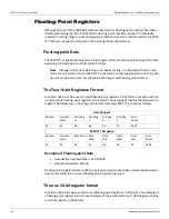
formats provide maximum system flexibility. In the two 16-bit registers format, function codes
03 and 04 are used to read floating-point registers while function code 16 is used to write
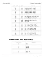
floating-point registers. In the one 32-bit register format, function code 65 is used to read
floating-point registers, while function code 66 is used to write floating-point registers.
Function codes 01, 02, 05, and 15 are used with status bits.
A complete description of all the preceding commands, except floating point, can be found in
the Modicon MODBUS Protocol Reference Guide, document number PI-MBUS-300 Rev B.
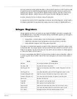
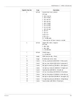
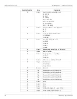
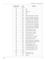
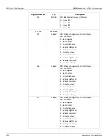
Integer Registers
Integer registers are the most commonly used type of MODBUS data and are supported by
most MODBUS hosts. In the 2920 FTT implementation, the MODBUS registers are arranged in
one of the following four formats:
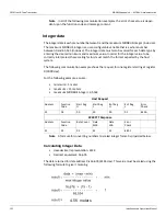
• Integer Data - a scaled number from 0 to the maximum MODBUS integer
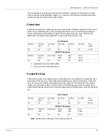
• Coded Data - Multiple choice configuration data chosen from a coded list
• Packed Bit Data - Register form of 16 packed single bits
The integer, and coded data registers contain all of the information needed to configure and
read process data. Any integer register may be read with function code 03 or function code 04.
These same registers may be written one at a time with function code 06 or multiple registers
can be written with function code 16.
For future compatibility, the 2920 FTT accepts reads and writes to reserved registers. Writes to
reserved registers have no effect. Reads from reserved registers will return undocumented
values.
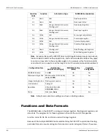
Term
Definition
Address
User-assigned address of the slave device
Function Code
Function the slave is to perform
Start Register (H)
High-order data address byte of the number of registers to read or
write
Start Register (L)
Low-order data address byte of the first register to read or write
Number of Registers (H)
High-order byte of the number of registers to read or write
Number of Registers (L)
Low-order byte of the number of registers to read or write
Byte Count
Number of data bytes
Data MSB
Data register's most significant byte
Data LSB
Data register's least significant byte
Status Bit (H)
High-order data address byte of the first bit to read or write
Status Bit (L)
Low-order data address byte of the first bit to read or write
Error Check
Message checksum CRC (Cyclical Redundancy Check)
Содержание 2920
Страница 2: ......
Страница 16: ...2920 Float Tape Transmitter 1 Introduction 6 Installation and Operations Manual...
Страница 114: ...2920 Float Tape Transmitter 6 Bi Phase Mark 104 Installation and Operations Manual...
Страница 120: ...2920 Float Tape Transmitter 7 MODBUS 110 Installation and Operations Manual...
Страница 126: ...2920 Float Tape Transmitter 9 L J TankWay 116 Installation and Operations Manual...
Страница 138: ...2920 Float Tape Transmitter 11 Configuration Calibration Level Limits and Outputs 128 Installation and Operations Manual...
Страница 148: ...2920 Float Tape Transmitter 12 Maintenance and Troubleshooting 138 Installation and Operations Manual...
Страница 158: ...2920 Float Tape Transmitter 14 Ordering Information 148 Installation and Operations Manual...
Страница 178: ...2920 Float Tape Transmitter MODBUSAppendix A MODBUS Implementation 168 Installation and Operations Manual...
Страница 193: ......