www.vanco1.com
800.626.6445
12
IR Matrix Switching
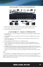
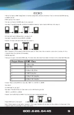
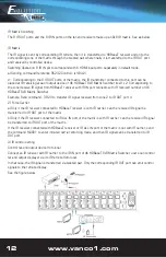
The 8 IR OUT ports and the 8 IR IN ports on the far-end receivers make up an 8x8 IR matrix. See as below:
IR Matrix
The IR signal is sent by corresponding IR remote, then it is transferred to HDBaseT receiver and on to the
corresponding zone of the matrix through the twisted pair where finally it is transferred to the IR OUT port
and received by controlled device.
Switching Operation: 8 IR IN ports correspond with 8 HDMI input ports separately in default mode.
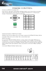
a) Sending command (reference RS232 Control): [x1]R[x2].
x1: Corresponding to the 8 IR OUT ports of the matrix, the IR transmitter connected to this port can be
placed at IR receiving area of output device or 4K HDBaseT 8x8 Matrix Switcher itself. x2: Corresponding to
the zone (receive IR signal from HDBaseT receiver with IR IN port connects with IR receiver) number of 4K
HDBaseT 8x8 Matrix Switcher.
Example: Send command - 3R2.II to transfer IR signal received from zone 2 to IR OUT port 3.
2) Force Carrier
a) Only if the IR receiver connected to HDBaseT receiver is with IR carrier, can the received IR signal be
transferred to IR OUT port of the matrix.
b) Only if the IR receiver connected to IR ALL IN port of the matrix is with IR carrier, can the received IR signal
be transferred to IR OUT port of the matrix.
If the IR receiver connected with HDBaseT receiver or IR ALL IN port of the matrix is not with IR carrier, send
the command %0901 to enter infrared carrier enforcing mode, and then IR signal can be transferred to IR
OUT port.
3) IR control setting
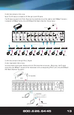
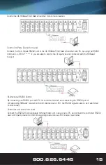
Control far-end output device from local
Connect an IR receiver with IR carrier to the IR IN port of 4K HDBaseT 8x8 Matrix Switcher, users can control
far-end output displayer via its IR remote from local.
In that case, the IR signal is transferred via twisted pair. Only the corresponding IR OUT port can emit control
signals to the remote display.
See the figure below:

