background image

Valueline IPC

3-18

PHOENIX CONTACT

2637_en_D

3.7

Intel

®

 Graphics Media Accelerator user interface

The Valueline IPC uses the Intel

® 

Graphics Media Accelerator video driver and has a variety 

of customization features available, including multiple displays. 

3.7.1

User interface

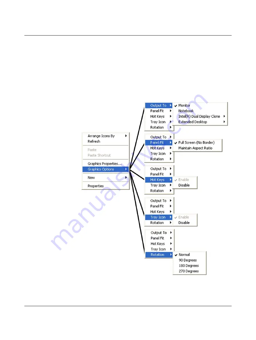
To access the video driver controls: 

right-click the desktop, move the pointer over “Graphics Options…” and navigate to the 

desired option. This provides a quick path to the desired setting. 

Figure 3-18

Graphic Media Accelerator direct select options

Содержание 2913181

Страница 1: ...User manual Valueline industrial PC Installation and configuration UM EN VALUELINE IPC Order No 9047058...

Страница 2: ...HOENIX CONTACT Valueline industrial PC Installation and configuration UM EN VALUELINE IPC D 9047058 Designation Version Order No Valueline IPC 2913108 User manual Designation Revision Order No This us...

Страница 3: ...www phoenixcontact com Published by PHOENIX CONTACT GmbH Co KG Flachsmarktstra e 8 32825 Blomberg GERMANY Should you have any suggestions or recommendations for improvement of the contents and layout...

Страница 4: ...ducts in your specific application in particular with regard to observ ing the applicable standards and regulations All information made available in the technical data is supplied without any accompa...

Страница 5: ...tivation 3 2 3 4 Firmware and software updates 3 3 3 5 Touchkit 3 3 3 5 1 Touchkit Setting 3 4 3 5 2 Touchkit Tools 3 7 3 5 3 Touchkit Edge Compensation 3 11 3 5 4 Touchkit Hardware 3 13 3 5 5 Touchki...

Страница 6: ...9 4 Maintenance 4 1 4 1 VL IPC components 4 2 4 1 1 Real time clock battery 4 5 4 1 2 Hard disk drive 4 5 4 2 BIOS configuration 4 6 4 2 1 Boot options 4 6 4 2 2 Power on after power fail options 4 7...

Страница 7: ...memory No operating system or a Windows operating system Size and type of mass storage Front bezel with or without USB slot Mounting options NVRAM non volatile RAM only available in some configuration...

Страница 8: ...r and optional PCI slots X10 COM1 X9 VGA X8 DVI D ERROR RUN HDD PWR X7 USB X5 USB X4 USB X6 USB X3 ETH X2 ETH X1 PWR 24VDC A B 4 8 7 6 1 3 2 9 5 PUSH 4 8 7 6 1 3 2 9 5 X10 COM1 X9 VGA X8 DVI D ERROR R...

Страница 9: ...RUN HDD PWR X7 USB X5 USB X4 USB X6 USB X3 ETH X2 ETH X1 PWR 24VDC A B X9 COM X8 VGA 4 8 7 6 1 3 2 9 5 PUSH Serial Port Status LEDs USB Ports 4 Ethernet Ports Power Switch 24 V DC Power Connector Acce...

Страница 10: ...8 7 6 1 3 2 9 5 PUSH Serial Port Status LEDs VGA Video USB Ports 4 Ethernet Ports Power Switch X9 COM X8 VGA ERROR RUN HDD PWR X7 USB X5 USB X4 USB X6 USB X3 ETH X2 ETH X1 PWR 24VDC A B 4 8 7 6 1 3 2...

Страница 11: ...dication Description ERROR Yellow Red Indicates reduced performance due to processor temperature Indicates an over temperature condition has caused the processor to shut down RUN Reserved for future u...

Страница 12: ...Valueline IPC 1 6 PHOENIX CONTACT 2637_en_D...

Страница 13: ...he VL IPC and air inlets and outlets to provide sufficient cooling 2 1 1 Temperature specifications Operational temperature limits depend on the specific configuration of the Valueline IPC see Table 2...

Страница 14: ...tach the VL IPC to the wall Anchor hardware must be smaller than 6 mm Ensure the attaching hardware is in the small section of the key holes 3 Tighten mounting screws Be careful not to overtighten the...

Страница 15: ...system permits installation of the VL IPC in a cabinet so the display panel is visible on the outside see Figure 2 2 Figure 2 2 Panel mount NOTE Connectors and switches must be accessible from the rea...

Страница 16: ...cted display Figure 2 3 Panel cut out dimensions for displays 2 From the front push the VL IPC through the opening Ensure the gasket is properly positioned in the groove Table 2 2 Cutout dimensions Di...

Страница 17: ...on the display and slide the clamp to the right see Figure 2 4 Clamps must be used in every slot Figure 2 4 Panel mount clamps 4 Tighten the screws with a screwdriver on all clamps alternating from on...

Страница 18: ...additional connections may be required to the PCI cards inserted in the PCI slots Figure 2 5 Interface connections 4 8 7 6 1 3 2 9 5 X10 COM1 X9 VGA X8 DVI D ERROR RUN HDD PWR X7 USB X5 USB X4 USB X6...

Страница 19: ...DVI D This port connects the VL IPC to an external digital display with a corresponding DVI D connector 2 2 2 External display External displays can be connected to the VL IPC to function as a deskto...

Страница 20: ...the unit Figure 2 6 Cover removal 3 Place the unit on a soft cloth on a flat horizontal surface with the ribbed surface cover up 4 Remove the four Phillips head screws 1 from the cover 2 and remove t...

Страница 21: ...cket from the bracket frame 5 c Line up the card s connectors with the PCI slot connector 6 Carefully push the card into the connector After it is fully inserted in the connector the card bracket shou...

Страница 22: ...a Remove the two Phillips head screws 1 holding the bracket frame 2 Remove the bracket frame and bracket 3 as an assembly b Remove the retaining screw and washer 4 and remove the bracket from the brac...

Страница 23: ...tion strip Carefully push the card into the connector 3 ensuring the frame assembly aligns with the mounting holes in the chassis and the card is properly seated in the connector e Secure the bracket...

Страница 24: ...Valueline IPC 2 12 PHOENIX CONTACT 2637_en_D...

Страница 25: ...connector pins A B are to be used with an uninterruptable power supply see Uninterruptable power supply on page 3 30 Ground screw The ground screw provides an earth ground for the VL IPC CAUTION The V...

Страница 26: ...are license and activation see Software license and activation on page 3 2 Upon completion of boot up the VL IPC runs the Touchkit screen calibration see 4 Points Calibration on page 3 8 3 3 Software...

Страница 27: ...ates can be found at the Phoenix Contact download center at www phoenixcontact net catalog Enter the part number or description of the device Valueline in the search field and navigate to the appropri...

Страница 28: ...ble when an audio acknowledgement to a screen touch is desired Click the desired check box to activate the desired mode Beep On Touch A beep is sounded when the screen is touched Beep On Release A bee...

Страница 29: ...area allowed for the second click relative to the first click Mouse modes Mouse modes allow configuration of mouse touch behavior One of five modes can be activate Figure 3 3 shows the button with No...

Страница 30: ...er to the right provides the coarsest movement Enable Auto Right Click Enables the Auto Right Click Time slider to set the time required for the a touch to be held and recognized as a right click This...

Страница 31: ...nd Operation 2637_en_D PHOENIX CONTACT 3 7 3 5 2 Touchkit Tools The Tools tab provides access to several tools for calibration and testing of the touch screen functionality Figure 3 5 Touchkit Tools d...

Страница 32: ...creen indicates the time remaining Clear and Calibrate Click the Clear and Calibrate button to erase a linearization This also starts the 4 Points Calibration utility Always use this button if changin...

Страница 33: ...ite screen with either 9 or 25 blinking touch points Figure 3 7 9 Points Calibration screen Touch and hold each point until the point stops blinking If a touch point is not touched within 30 seconds t...

Страница 34: ...the calibration and other settings of the touch screen click the Draw Test button This utility opens a scratch pad for testing purposes Touch the screen and perform typical operations to evaluate the...

Страница 35: ...e Compensation The Edge Compensation tab sets the cursor overshoot and undershoot touch points along the edge of the screen This helps to compensate for the difficulty sometimes experienced in touchin...

Страница 36: ...lay position can be shifted along either the X or Y axis displayed by pixel Figure 3 10 Edge compensation example Click the Support Edge Compensation button to activate deactivate the edge compensatio...

Страница 37: ...plays controller and firmware information about the touch screen This information may be required if problems occur Figure 3 11 Touchkit Hardware dialog box Click the Hardware Setting button to open t...

Страница 38: ...icon In WIndows 7 right click the eGalaxTouch icon If the icon is not in the notification area click the Start button and In Windows XP navigate to the All Programs Touchkit folder and then click the...

Страница 39: ...odes on page 3 5 Beep Selects the Beep mode see Audio acknowledgement on page 3 4 Auto Right Click When checked touch the screen for an extended time period simulates a right click see Mouse modes on...

Страница 40: ...ght Click tool The floating Right Click tool provides right click functionality and a way to launch the on screen keyboard To perform a right click touch the Right Click button The next touch is the s...

Страница 41: ...e dialog box To prevent the dialog box from appearing again touch the Don t show this message again check box before touching the OK button Figure 3 16 The On Screen Keyboard dialog box The On Screen...

Страница 42: ...ideo driver and has a variety of customization features available including multiple displays 3 7 1 User interface To access the video driver controls right click the desktop move the pointer over Gra...

Страница 43: ...menu press the Cntl Alt F12 keys on screen keyboard or external keyboard Figure 3 19 Graphics Media Accelerator main user interface screen The user interface screen can be divided into a top and bott...

Страница 44: ...for an analog display connected to the VGA port Digital Display this is for a digital display connected to the DVI D port If a digital display is not connected to the Valueline IPC this option will no...

Страница 45: ...3 21 Display settings for a single display The drop down boxes only display selections pertinent to the particular display being configured For rotation the Enable Rotation check box must be checked...

Страница 46: ...VGA or DVI D ports see External display on page 2 7 The configuration options for multiple displays are Twin outputs the same content with the same configuration settings to displays connected to the...

Страница 47: ...vice and which is the Secondary Device using the drop down menus Note that the Primary Device typically has more options Also some options require a digital device be connected to the DVI D port befor...

Страница 48: ...tings for one display of a multiple display setup The drop down boxes for each setting will only display items that are valid for the hardware configuration For rotation the Enable Rotation check box...

Страница 49: ...ntrast settings Figure 3 25 Color corrections Click on the top tab to select the desired display for configuring Dual Display Clone or Extended Desktop selections Click the Apply button to apply the s...

Страница 50: ...make changes to video running in a separate pop up window 3 7 6 Schemes Configuration selections can be saved as schemes Schemes can be recalled when desired activating the saved settings without the...

Страница 51: ...pre defined assignable hot keys to initially select a single active display and degrees of rotation for that display To change an assignment 1 Click the Hot Keys tab on the left side of the screen Fig...

Страница 52: ...ld at the right and then press the desired third key to create the hot key combination for the selected action The third key can be a letter number function or arrow key up down left or right 6 Click...

Страница 53: ...ion as read from a connected display s Extended Display Identification Data EDID Monitor The EDID contained in a display connected to the VGA port is reported on this tab including supported resolutio...

Страница 54: ...eneric 24 V DC function diagram Phoenix Contact has two product lines recommended for the Valueline The TRIO UPS for load currents up to 5 A combines the power supply and switching unit into a single...

Страница 55: ...the shutdown procedure Serial port DB 9 This connection method provides additional communication between the Valueline IPC and the uninterruptable power supply As in the power connection method when t...

Страница 56: ...e an optional program before the VL IPC begins the shutdown procedure Shuts down the UPS When the VL IPC turns off it can also turn off the UPS through an external dry contact while the UPS is in Batt...

Страница 57: ...10 COM1 X9 VGA 4 8 7 6 1 3 2 9 5 24V 11 21 31 R1 R2 12 13 22 23 32 33 Relay NOTE The Valueline IPC serial port and pins A B on the power connector cannot accept 24 V The un interruptible power supply...

Страница 58: ...In the Select model field select Custom In the On port field select either COM1 for the DB 9 connector or COM2 for the power connector pins A B Click the Next button to proceed to the next screen Fig...

Страница 59: ...dialog box 7 Click the Configure button 8 The suggested configuration of the driver is as follows Click the Enable all notifications check box to display a message when the VL IPC goes to battery pow...

Страница 60: ...ows system32 and have a file extension of exe com bat or cmd Administrative privileges may be required Command files that initiate a dialog box and require user input cannot be used The command file m...

Страница 61: ...e notification area to open the UPS CONF interface 6 The software should be communicating with the TRIO UPS and displaying the current operating status at the bottom of the interface 7 Set the buffer...

Страница 62: ...these steps 1 Open the access door 2 Press the eject button to remove an optical disk Figure 3 41 Optical drive eject button 3 Insert the CD DVD in the proper orientation for the drive The recorded r...

Страница 63: ...TE CompactFlash cards are handled like hard drives in a Valueline IPC and are therefore not hot swappable Ejecting a CompactFlash before the VL IPC is powered down could result in data loss 4 8 7 6 1...

Страница 64: ...ash the BIOS must be properly configured see BIOS configuration on page 4 6 To remove a card from slot 0 use a small needle nose pliers and carefully pull the card straight out To remove a card from s...

Страница 65: ...aintenance 2637_en_D PHOENIX CONTACT 4 1 4 Maintenance The Valueline IPC has several removable components To access some of these components it may be necessary to remove cables connected to the VL IP...

Страница 66: ...device a removable hard disk bay and the RTC battery Figure 4 1 VL IPC with access door open 4 8 7 6 1 3 2 9 5 X10 COM1 X9 VGA X8 DVI D ERROR RUN HDD PWR X7 USB X5 USB X4 USB X6 USB X3 ETH X2 ETH X1...

Страница 67: ...ss door open X9 COM X8 VGA ERROR RUN HDD PWR X7 USB X5 USB X4 USB X6 USB X3 ETH X2 ETH X1 PWR 24VDC A B 4 8 7 6 1 3 2 9 5 Serial Port VGA Video Status LEDs USB Ports 4 Ethernet Ports Power Switch RTC...

Страница 68: ...ard chassis with access door open X9 COM X8 VGA ERROR RUN HDD PWR X7 USB X5 USB X4 USB X6 USB X3 ETH X2 ETH X1 PWR 24VDC A B 4 8 7 6 1 3 2 9 5 Serial Port VGA Video Status LEDs USB Ports 4 Ethernet Po...

Страница 69: ...e the battery with the same type CR2032 3V Lithium oriented as shown in Figure 4 4 Figure 4 4 Insert RTC battery as shown 4 1 2 Hard disk drive The hard drive installs in a tray that is easily removab...

Страница 70: ...mmend changing BIOS configuration settings without specific instruction from Phoenix Contact Technical Services this is something that may be necessary To access the BIOS configuration there must be a...

Страница 71: ...key to save the change and exit the submenu 6 When ready press the F10 key to save changes exit and continue booting the VL IPC Manual boot mode Manual boot mode overrides automatic boot mode and allo...

Страница 72: ...plays the desktop and then turns off If the UPS is in battery mode then this is a normal action as controlled by the operating system s generic UPS driver to conserve battery power short time to do th...

Страница 73: ...is charged Bat Charge LED on the QUINT DC UPS is off Remove power from the UPS which changes the state of the Bat mode signal to display On Battery as the current power source Make sure the VL IPC sh...

Страница 74: ...Valueline IPC 4 10 PHOENIX CONTACT 2637_en_D...

Страница 75: ...helf installation replacement VL BOOKSHELF MOUNTING KIT 2913160 1 Mounting kit bookshelf with PCI slots installation replacement VL BOOKSHELF MOUNTING KIT EXPANSION 2913164 1 HDD tray kit removable HD...

Страница 76: ...dard 2009 XP Windows Embedded Standard 7 Processor configurable option 1 60 GHz Intel Atom N270 533FSB 512 kB L2 Cache 1 06 GHz Intel Celeron M 533FSB 1 MB L2 Cache 1 5 GHz Intel Core 2 Duo 667FSB 4 M...

Страница 77: ...esistive touch screen with serial USB interface Brightness 300 Cd m Number of colors 16 7 million Contrast ratio 1300 1 View angle horizontal vertical CR 10 89 89 Installation cutout dimensions width...

Страница 78: ...Contrast ratio 600 1 View angle horizontal vertical CR 10 70 60 Installation cutout dimensions width x height 334 0 x 253 0 mm Outside bezel dimensions width x height x depth 365 x 282 x 10 mm Backlig...

Страница 79: ...rface connections 2 6 Figure 2 6 Cover removal 2 8 Figure 2 7 Side panel and bracket removal 2 9 Figure 2 8 PCI slot 0 removal 2 10 Figure 2 9 PCI slot 0 card installation 2 11 Section 3 Figure 3 1 VL...

Страница 80: ...lay of a multiple display setup 3 24 Figure 3 25 Color corrections 3 25 Figure 3 26 OpenGL Settings dialog box 3 25 Figure 3 27 Overlay Settings dialog box 3 26 Figure 3 28 Scheme Options dialog box 3...

Страница 81: ...door open 4 2 Figure 4 2 VL IPC with Atom processor in Atom enhanced chassis with access door open 4 3 Figure 4 3 VL IPC with Atom processor in Atom standard chassis with access door open 4 4 Figure 4...

Страница 82: ...Valueline IPC B 4 PHOENIX CONTACT 2637_en_D...

Страница 83: ...es Section 1 Table 1 1 LED status indicators 1 5 Section 2 Table 2 1 Temperature limits 2 1 Table 2 2 Cutout dimensions 2 4 Section 3 Table 3 1 Touchkit menu functions 3 15 Table 3 2 Power requirement...

Страница 84: ...Valueline IPC B 6 PHOENIX CONTACT 2637_en_D...

Отзывы: