Sabre
Sabre
Sabre
Sabre----44
44
44
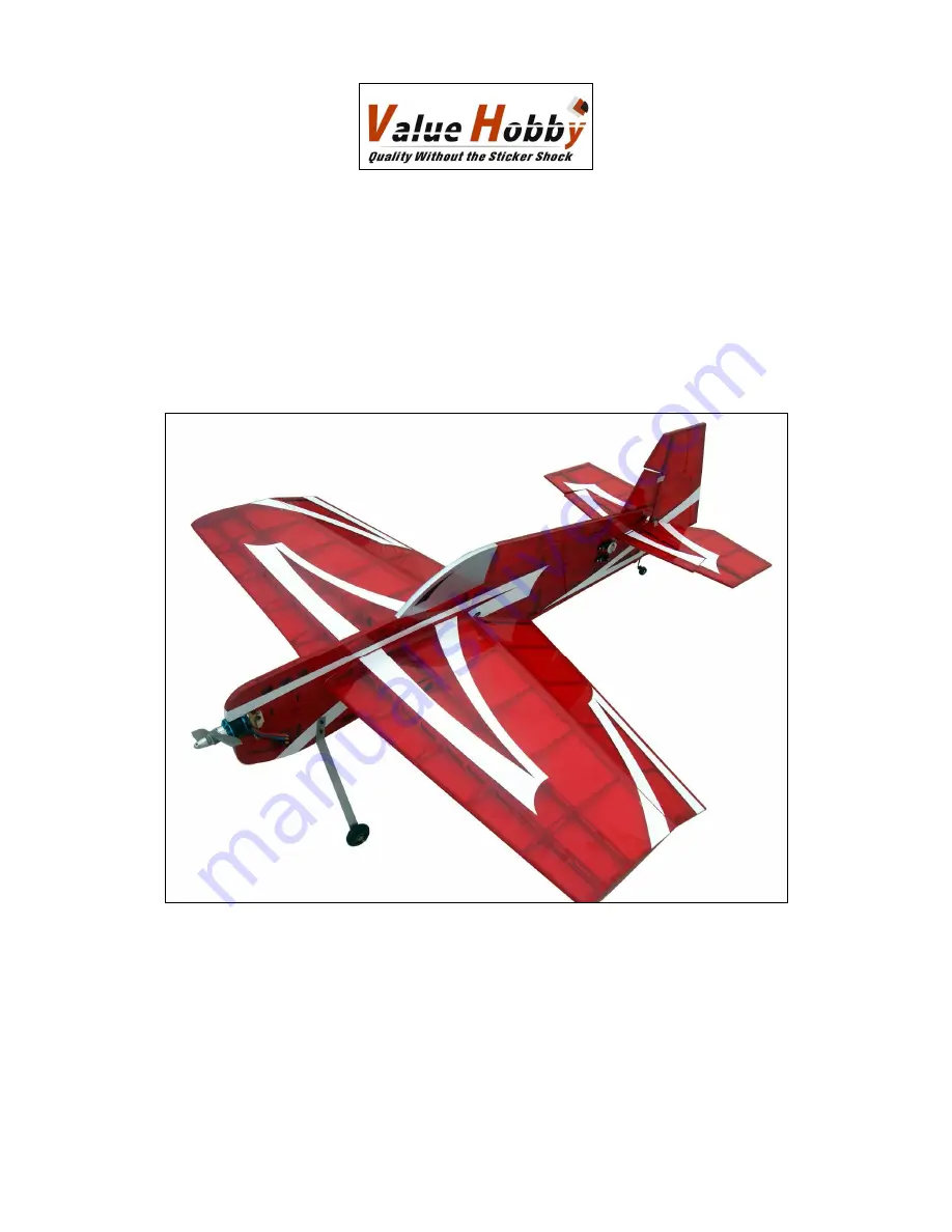
44 3D Profile
3D Profile
3D Profile
3D Profile
Almost-Ready-to-Fly
Instruction Manual
Wingspan: 1100mm (43.31in)
Length: 1193mm (46.97in)
Wing Area: 40.08 sq dm (621.24sq in)
Flying Weight: 1100g-1250g (2.43lb-2.76lb)


