background image

8

Release 07/22

MashFlex

Wire Rope Safety Barrier

Wire Rope Safety Barrier

Wire Rope Safety Barrier

ASH LE

I N G A L   C I V I L   P R O D U C T S

ASH LE

I N G A L   C I V I L   P R O D U C T S

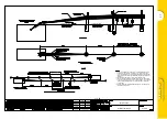
5.0   End Terminals

End terminals are used to anchor the system and provide 
a soft gating impact to prevent vehicles from launching 
or snagging upon impact with MashFlex.

5.1   MASH TL3 Terminal

The TL3 Terminal  has been  crash tested  to meet  the 
requirements of MASH TL3. It can be used on all new 
installations or retrofitted to existing MashFlex or 
Flexfence installations.
The TL3 Terminal gradually tapers the cables from full 
height to an anchor bracket located at ground level over 
10m. Refer drawing WR-MF-050 general arrangement 
and point of redirection.
The TL3 Terminal has demonstrated an ability to provide a 
soft, gating impact without releasing the cables from the  
anchor point. This non-release feature allows the system 
to remain anchored following design impacts.
This important feature contrasts terminals that are 
designed to release the cables for end-on impacts. Once 
these terminals release the cables their ability to provide 
continued containment and redirection for errant 
vehicles is compromised.

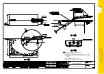
5.2   Standard Terminal

The Standard Terminal is designed to provide the 
necessary cable anchoring to redirect errant vehicles that 
impact the wire rope barrier within the length-of-need 
section. Use of this terminal is limited to locations where 
geometric constraints limit the use of the TL3 Terminal 
and it should only be used where it is shielded behind 
another barrier and cannot be impacted.

6.0  Installation

The  following  written instructions should  be  read in 
conjunction with the MashFlex drawings.
A Safe Work Method Statement is available upon request 
to assist in the safe assembly of MashFlex.
The installation of MashFlex requires specific tooling for 
the swaging of the end fittings onto the cables, and also 
for applying the appropriate tension at the end of the 
installation. This equipment is known as the FlexFence 
Tension Unit and FlexFence Swaging Unit. Please contact 
your nearest Ingal representative for the safe operating 
instructions for this equipment.

6.1   Site Preparation

The approach terrain to the barrier should be level, 
otherwise a maximum grading of 1V:10H is permitted. 
Steeper slopes may result in the vehicle impacting the 
barrier at other than the design height.

6.2  Horizontal and Vertical Alignment Criteria

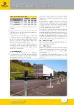
The length and/or horizontal curvature of an installation 
of wire rope barrier may increase the dynamic deflection 
of the barrier. In addition, horizontal curves may place 
more lateral load on the post foundations. Horizontal 
curve of less than 200m radius are not recommended.
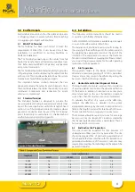
To calculate the effect of a curve on the deflection, 
multiply the deflections as detailed on the system 
arrangement drawings by the curve correction factor in 
Table 3, the length column is the total length of the run. 
These correction factors only apply to convex curves
The minimum allowable sag vertical curve for wire rope 
barriers is ≥ 30m. (K = length of VC in metres divided by 
the change in grade expressed as a percentage). There is 
no K value limit for crest curves.

6.3   End Anchor Site Preparation

The site should be inspected for the presence of 
underground utilities prior to any excavation. The site 
should be prepared free  of obstructing vegetation and 
other hazards that may interfere with the installation or 
operational performance of the system. Some sites may 
require minor grading if installed beyond the edge of the 
pavement shoulder.

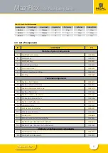
Table 3: Length and Curve Correction Factors

Length (m)

Convex Curve Radius (m)

200-299

300-449

450-749

750+

0-100

1.4

1.3

1.1

1.0

101-200

1.6

1.4

1.2

1.0

201-300

1.6

1.5

1.3

1.1

301-500

1.7

1.5

1.3

1.2

501-1000

1.8

1.6

1.4

1.2

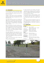
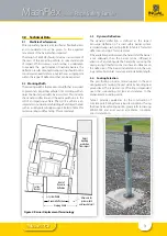
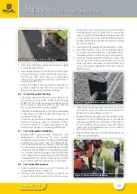
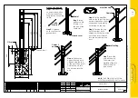
Figure 3: Standard Terminal

Содержание INGAL MashFlex MASH TL3

Страница 1: ...ww ingalcivil com au Release 07 22 MashFlex is licensed to Ingal Civil Products by Blue Systems Inc of Sweden ProductManual Wire Rope Safety Barrier Wire Rope Safety Barrier MashFlex MASH TL3 MASH TL4...

Страница 2: ...to length stainless steel end fittings are machine swaged and the ropes are tensioned MashFlex is a 4 rope barrier assessed in accordance with MASH Test Level 3 TL3 and TL4 TestLevel3comprisestwotests...

Страница 3: ...ion of a road safety barrier system recorded during crash testing Refer to Table 2 for tested deflections and Fig 2 for more detail If the available space between the hazard and the barrier is not ade...

Страница 4: ...ength of barrier required to protect from this hazard The most common method is the run out length method and an alternative is a method based on angle of departure Prior to design or installation des...

Страница 5: ...e 10001560 T6 TL3 Flexfence Ground Cover 10001566 T7 Flexfence Anchor Bracket 10001574 T8 Cable End Fitting 10001530 T9 M24 Stainless Steel Washer 10001531 T10 M24 Stainless Steel Nut 10001532 T11 Hoo...

Страница 6: ...p ID B PN 10009397 MashFlexPlug ID C PN 10009421 MashFlexPlasticSleeve ID D PN 10009420 ReoRing ID G PN 10001580 MashFlexDrivenSleeve ID ZA PN 10007593 MashFlexPostonBaseplate ID ZB PN 10009425 PostGr...

Страница 7: ...PN 10001574 CableEndFitting ID T8 PN 10001530 FlexfenceSteelSpreader4Rope ID T3 PN 10001570 M24StainlessSteelWasher ID T9 PN 10001531 FlexfencePlasticCap ID T4 PN 10001563 M24StainlessSteelNut ID T10...

Страница 8: ...so for applying the appropriate tension at the end of the installation This equipment is known as the FlexFence Tension Unit and FlexFence Swaging Unit Please contact your nearest Ingal representative...

Страница 9: ...or block drawing 2 Ifinstallingtherectangularanchorblock clipoutseveral grids of the reomesh square to fit over the anchor bracket as shown in Ingal drawingWR STD 62 Figure 4 Clipping of Reomesh 3 Att...

Страница 10: ...e foundation via four M20 G5 8 studs chemically anchored using Hilti HY 200R refer drawing WR MF 003 Anchor studs shall be installed in accordance with the manufacturer s instructions 6 8 Post Assembl...

Страница 11: ...11 Release 07 22 MashFlex Wire Rope Safety Barrier Figure 10 Figure 11 Figure 12 Figure 13...

Страница 12: ...12 Release 07 22 MashFlex Wire Rope Safety Barrier Figure 14 Figure 15 Figure 16 Figure 17...

Страница 13: ...etting of the tension bay for this cable will help expedite the tensioning process It may be necessary to attach temporary clamps one post back from the tension bay location prior to cutting in order...

Страница 14: ...0 10 29kN 316 15 27kN 293 20 25kN 270 25 23kN 247 30 21kN 224 35 19kN 201 40 17kN 177 6 10 Clean up and Waste Materials Recycle reuse or dispose of all surplus material rubbish and other debris in acc...

Страница 15: ...sion annually This can be undertaken using the FlexFence Tension Unit 7 2 Bush Fire Damage 1 The performance of galvanized coatings when subjected to bushfire depends on a number of factors such as fl...

Страница 16: ...fthedamagedoruncoatedareasdoesnotexceed 10cm2 0 5 ofthetotalsurfacearea Thesumtotalofthedamagedoruncoatedareasexceeds10cm2 0 5 ofthetotalsurfacearea An organic zinc rich epoxy paint complying with AS...

Страница 17: ...s frame been inserted between the top and second from top cable Yes No Have post caps been attached to the posts Yes No Has the anchor cable locking bolt been installed with nuts tightened to snug Yes...

Страница 18: ...QWR WKH VORW DQG LQWR WKH SRVW DEOH 0DVK OH DS 6WHS 3RVLWLRQ WKH FDS XQWLO LWV WRS VORW LV DOOLJQHG ZLWK WKH WRS RI WKH SRVW 7KHQ LQVHUW DEOHV DQG LQWR WKH VORW DQG LQWR WKH SRVW DEOHV DQG 6WHS QVHUW...

Страница 19: ...19 Release 07 22...

Страница 20: ...VHG RQ WKH FDS 6WHS 3RVLWLRQ WKH FDS XQWLO LWV ERWWRP VORW LV DOOLJQHG ZLWK WKH WRS RI WKH SRVW 7KHQ LQVHUW DEOH LQWR WKH VORW DQG LQWR WKH SRVW 6WHS QVHUW ERWWRP FDEOH DEOH WR WKH HQG RI WKH FDEOH VO...

Страница 21: ...E ANCHOR TO BE 2100mm FOR A MASHFLEX INSTALLATION WITH A POST SPACING OF 2 5m CONTACT YOUR ICP REPRESENTATIVE FOR OVERLAP WHEN USING A DIFFERENT POST SPACING 4 DISTANCE BETWEEN TERMINALS MUST BE GREAT...

Страница 22: ...ION ONLY C I V I L P R O D U C T S COMPANY valmont A MASHFLEX WRSB TENSION PANEL ARRANGEMENT WR MF 059 0 N T S A3 14 11 2019 VB LG 14 11 2019 LG 14 11 2019 F ENGINEERING SALES MARKETING DRAWINGS MASHF...

Страница 23: ...ROVED DRAWN SCALE Rev NAME DATE CHECKED ISSUE FOR INFORMATION ONLY C I V I L P R O D U C T S COMPANY valmont A FLEXFENCE MASHFLEX WRSB RECTANGULAR TYPE 1 ANCHOR BLOCK WR STD 62 8 N T S A3 02 11 2011 A...

Страница 24: ...RWISE CONTACT A QUALIFIED GEOTECHNICAL ENGINEER 6 FOR ADDITIONAL GUIDANCE PLEASE CONTACT YOUR LOCAL INGAL SALES REPRESENTATIVE 7 ALL UNITS ARE IN MM UNLESS NOTED OTHERWISE 8 INGAL CIVIL PRODUCTS MARKE...

Страница 25: ...6 27 5 6 63 7 16 21 N1 0 17 5 7 03 62 72 0 7 25 7 5 48 5 0 176 25 6 72 67 1 5 62 0 5 1 25 25 506 5 9 5 0 7 5 0LQ 5 3 67 7 1 1 5 1 5 9 7 6 5 37 21 33529 5 9 6 216 5 5 1 6 5 1 180 5 5 5 1 5 1 6 5 6 52 0...

Страница 26: ...26 Release 07 22 Notes...

Страница 27: ...27 Release 07 22 Notes...

Страница 28: ...elaide NT Brisbane Melbourne Newcastle Perth Sydney Wagga Auckland Christchurch Head Office Sydney 57 65 Airds Road Minto NSW 2566 Ph 61 2 9827 3333 Fax 61 2 9827 3300 Local call within Australia 1300...

Отзывы: