Wire Rope Safety Barrier
Wire Rope Safety Barrier
ASH LE
I N G A L C I V I L P R O D U C T S
ASH LE
I N G A L C I V I L P R O D U C T S
9
Release 07/22
MashFlex
Wire Rope Safety Barrier
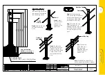
Vehicles impacting the end of the terminals will normally
continue behind and beyond the barrier and may
encounter non-traversable terrain or other roadside
hazards. It is recommended that the guidelines as stated
in AS/NZS 3845 for the installation of gating safety barrier
end terminals be observed.
AS/NZS3845 requires that a Hazard Free Zone
‘immediately behind the terminal… should be
reasonably traversable and free from fixed object hazards.
If a clear runout is not possible, this area should be similar
in character to adjacent unshielded roadside areas.’
6.4 Construction of Anchor Blocks
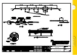
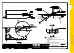
MashFlex is available with a variety of anchor block
designs. These include;
1. Default block - Type 3 - WR-STD-64
2. Poor soil conditions - Type 1 - WR-STD-62
3. Spacial limitations - Pier - WR-STD-82
The selection of a suitable design will depend upon soil
type, refer anchor drawings for minimum conditions.
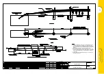
Typically, the alignment of the anchor block will follow
the same alignment as the length of need section. If site
conditions require the anchor block to be offset to the
length of need section, a 200m radius can be introduced
upstream from the end anchor until the desired offset
angle is achieved. The fence can then be tapered at a
constant rate to achieve the required offset distance.
The construction sequence is as follows;
1. Excavate the anchor hole in accordance with the
chosen anchor block drawing.
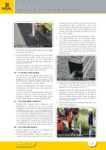
2. If installing the rectangular anchor block, clip out several
grids of the reomesh square to fit over the anchor
bracket as shown in Ingal drawing WR-STD-62.
Figure 4: Clipping of Reomesh
3. Attach 3 off M20 x 550mm hook bolts to the base of
the anchor bracket using 2 off M20 nuts per hook bolt.
One M20 nut is used either side of the anchor bracket
to secure each hook bolt.
4. Using formwork, suspend the anchor bracket and
reomesh, ensuring the anchor bracket levelling plate
is at the same longitudinal grade as the roadway. The
position of the anchor bracket is to be in accordance
with the anchor block drawing.
Figure 5: Placement of Anchor Bracket
5. To prevent flotation or dislodgement during the
concrete pour, drive a shortened star picket into the
base or side of the excavation and use tie wire to
secure the bracket.
6. Pour concrete into the excavation and vibrate. Ensure
that the anchor bracket has remained secure.
7. Trowel the surface of the anchor block and shape to
provide fall way from the anchor bracket.
Figure 6: Trowelling of the Anchor Block
6.5 Construction of Concrete Post Footings
1. Establish post spacing in accordance with expected
dynamic deflections and excavate postholes to the
dimensions in accordance with Table 1. Note that the
height of the footing must be within 20mm of the
design reference height.
If the sides of the postholes are seen to fall away into
the hole upon coring/excavation, creating a ‘coning’
or tapering of the hole, the hole depth should be
increased to 750mm.
2. Pour concrete into each hole.
Содержание INGAL MashFlex MASH TL3
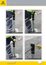
Страница 11: ...11 Release 07 22 MashFlex Wire Rope Safety Barrier Figure 10 Figure 11 Figure 12 Figure 13...
Страница 12: ...12 Release 07 22 MashFlex Wire Rope Safety Barrier Figure 14 Figure 15 Figure 16 Figure 17...
Страница 19: ...19 Release 07 22...
Страница 26: ...26 Release 07 22 Notes...
Страница 27: ...27 Release 07 22 Notes...


