valmont INGAL MashFlex MASH TL3 Скачать руководство пользователя страница 4

4

Release 07/22

MashFlex

Wire Rope Safety Barrier

Wire Rope Safety Barrier

Wire Rope Safety Barrier

ASH LE

I N G A L   C I V I L   P R O D U C T S

ASH LE

I N G A L   C I V I L   P R O D U C T S

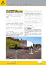
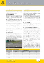
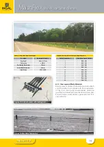
Table 1: Post Footing Selection Guide

Centre of Post Footing to

Rounding Point

Standard Soil

Weak Soil

Dia

Depth

Dia

Depth

Less than 0.5m

300

600

300

750

Greater than 0.5m

300

600

300

750

The minimum concrete compressive strength at 28 days 
is 30Mpa.
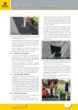
In the event that the soil type cannot be verified, then 
a post pull-over test can be conducted  to validate the 
structural capacity of the footing.
A pull-over test is conducted  by applying a load to the 
top of the post whilst positioned in the proposed footing 
design. The footing is required to remain stable until the 
post yields. Once the post yields, the footing has been 
subjected to its maximum potential load.
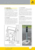
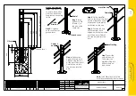
For locations where the typical 600mm deep post 
foundation cannot be installed, a strip footing with post 
on baseplates is an alternative option, refer drawing 
WR-MF-003 for further detail.

3.5    Minimum Length

There are two geometric methods used to determine 
the likely trajectory of a vehicle that leaves the road in the 
vicinity of a roadside hazard and the minimum length of 
barrier required to protect from this hazard. 

The most common method is the run-out length 
method and an alternative is a method based on angle 
of departure.
Prior to design or installation, designers should consult 
the relevant road controlling authority to establish the 
local jurisdictional practice as the methods may result 
in different lengths. Both methods are detailed in the 
Austroads Guide to Road Design – Part 6.3.
For instances where geometric constraints limit the 
installation of the recommended length under the 
above design methods, the absolute minimum length of 
minimum length of need for a run of MashFlex is 70m, this 
includes a TL3 Terminal on both ends. These installations 
should be considered within the requirements of the 
road controlling authority’s Extended Design Domain.

3.6   Maximum Length

Please refer to your local road controlling authority for their 
max run length recommendation.
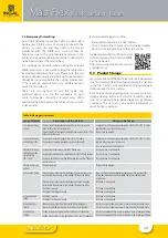
3.7   Point-of-Need

MashFlex  is designed  to  contain  and  redirect errant 
vehicles away from road side hazards. The location along 
the barrier system that redirection occurs is known as the 
point-of-need.
The point-of need for the MashFlex system is 11.73m 
from the anchor point when using the MASH TL3 End 
Terminal.

Содержание INGAL MashFlex MASH TL3

Страница 1: ...ww ingalcivil com au Release 07 22 MashFlex is licensed to Ingal Civil Products by Blue Systems Inc of Sweden ProductManual Wire Rope Safety Barrier Wire Rope Safety Barrier MashFlex MASH TL3 MASH TL4...

Страница 2: ...to length stainless steel end fittings are machine swaged and the ropes are tensioned MashFlex is a 4 rope barrier assessed in accordance with MASH Test Level 3 TL3 and TL4 TestLevel3comprisestwotests...

Страница 3: ...ion of a road safety barrier system recorded during crash testing Refer to Table 2 for tested deflections and Fig 2 for more detail If the available space between the hazard and the barrier is not ade...

Страница 4: ...ength of barrier required to protect from this hazard The most common method is the run out length method and an alternative is a method based on angle of departure Prior to design or installation des...

Страница 5: ...e 10001560 T6 TL3 Flexfence Ground Cover 10001566 T7 Flexfence Anchor Bracket 10001574 T8 Cable End Fitting 10001530 T9 M24 Stainless Steel Washer 10001531 T10 M24 Stainless Steel Nut 10001532 T11 Hoo...

Страница 6: ...p ID B PN 10009397 MashFlexPlug ID C PN 10009421 MashFlexPlasticSleeve ID D PN 10009420 ReoRing ID G PN 10001580 MashFlexDrivenSleeve ID ZA PN 10007593 MashFlexPostonBaseplate ID ZB PN 10009425 PostGr...

Страница 7: ...PN 10001574 CableEndFitting ID T8 PN 10001530 FlexfenceSteelSpreader4Rope ID T3 PN 10001570 M24StainlessSteelWasher ID T9 PN 10001531 FlexfencePlasticCap ID T4 PN 10001563 M24StainlessSteelNut ID T10...

Страница 8: ...so for applying the appropriate tension at the end of the installation This equipment is known as the FlexFence Tension Unit and FlexFence Swaging Unit Please contact your nearest Ingal representative...

Страница 9: ...or block drawing 2 Ifinstallingtherectangularanchorblock clipoutseveral grids of the reomesh square to fit over the anchor bracket as shown in Ingal drawingWR STD 62 Figure 4 Clipping of Reomesh 3 Att...

Страница 10: ...e foundation via four M20 G5 8 studs chemically anchored using Hilti HY 200R refer drawing WR MF 003 Anchor studs shall be installed in accordance with the manufacturer s instructions 6 8 Post Assembl...

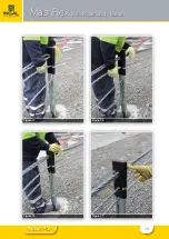
Страница 11: ...11 Release 07 22 MashFlex Wire Rope Safety Barrier Figure 10 Figure 11 Figure 12 Figure 13...

Страница 12: ...12 Release 07 22 MashFlex Wire Rope Safety Barrier Figure 14 Figure 15 Figure 16 Figure 17...

Страница 13: ...etting of the tension bay for this cable will help expedite the tensioning process It may be necessary to attach temporary clamps one post back from the tension bay location prior to cutting in order...

Страница 14: ...0 10 29kN 316 15 27kN 293 20 25kN 270 25 23kN 247 30 21kN 224 35 19kN 201 40 17kN 177 6 10 Clean up and Waste Materials Recycle reuse or dispose of all surplus material rubbish and other debris in acc...

Страница 15: ...sion annually This can be undertaken using the FlexFence Tension Unit 7 2 Bush Fire Damage 1 The performance of galvanized coatings when subjected to bushfire depends on a number of factors such as fl...

Страница 16: ...fthedamagedoruncoatedareasdoesnotexceed 10cm2 0 5 ofthetotalsurfacearea Thesumtotalofthedamagedoruncoatedareasexceeds10cm2 0 5 ofthetotalsurfacearea An organic zinc rich epoxy paint complying with AS...

Страница 17: ...s frame been inserted between the top and second from top cable Yes No Have post caps been attached to the posts Yes No Has the anchor cable locking bolt been installed with nuts tightened to snug Yes...

Страница 18: ...QWR WKH VORW DQG LQWR WKH SRVW DEOH 0DVK OH DS 6WHS 3RVLWLRQ WKH FDS XQWLO LWV WRS VORW LV DOOLJQHG ZLWK WKH WRS RI WKH SRVW 7KHQ LQVHUW DEOHV DQG LQWR WKH VORW DQG LQWR WKH SRVW DEOHV DQG 6WHS QVHUW...

Страница 19: ...19 Release 07 22...

Страница 20: ...VHG RQ WKH FDS 6WHS 3RVLWLRQ WKH FDS XQWLO LWV ERWWRP VORW LV DOOLJQHG ZLWK WKH WRS RI WKH SRVW 7KHQ LQVHUW DEOH LQWR WKH VORW DQG LQWR WKH SRVW 6WHS QVHUW ERWWRP FDEOH DEOH WR WKH HQG RI WKH FDEOH VO...

Страница 21: ...E ANCHOR TO BE 2100mm FOR A MASHFLEX INSTALLATION WITH A POST SPACING OF 2 5m CONTACT YOUR ICP REPRESENTATIVE FOR OVERLAP WHEN USING A DIFFERENT POST SPACING 4 DISTANCE BETWEEN TERMINALS MUST BE GREAT...

Страница 22: ...ION ONLY C I V I L P R O D U C T S COMPANY valmont A MASHFLEX WRSB TENSION PANEL ARRANGEMENT WR MF 059 0 N T S A3 14 11 2019 VB LG 14 11 2019 LG 14 11 2019 F ENGINEERING SALES MARKETING DRAWINGS MASHF...

Страница 23: ...ROVED DRAWN SCALE Rev NAME DATE CHECKED ISSUE FOR INFORMATION ONLY C I V I L P R O D U C T S COMPANY valmont A FLEXFENCE MASHFLEX WRSB RECTANGULAR TYPE 1 ANCHOR BLOCK WR STD 62 8 N T S A3 02 11 2011 A...

Страница 24: ...RWISE CONTACT A QUALIFIED GEOTECHNICAL ENGINEER 6 FOR ADDITIONAL GUIDANCE PLEASE CONTACT YOUR LOCAL INGAL SALES REPRESENTATIVE 7 ALL UNITS ARE IN MM UNLESS NOTED OTHERWISE 8 INGAL CIVIL PRODUCTS MARKE...

Страница 25: ...6 27 5 6 63 7 16 21 N1 0 17 5 7 03 62 72 0 7 25 7 5 48 5 0 176 25 6 72 67 1 5 62 0 5 1 25 25 506 5 9 5 0 7 5 0LQ 5 3 67 7 1 1 5 1 5 9 7 6 5 37 21 33529 5 9 6 216 5 5 1 6 5 1 180 5 5 5 1 5 1 6 5 6 52 0...

Страница 26: ...26 Release 07 22 Notes...

Страница 27: ...27 Release 07 22 Notes...

Страница 28: ...elaide NT Brisbane Melbourne Newcastle Perth Sydney Wagga Auckland Christchurch Head Office Sydney 57 65 Airds Road Minto NSW 2566 Ph 61 2 9827 3333 Fax 61 2 9827 3300 Local call within Australia 1300...

Отзывы: