Wire Rope Safety Barrier
Wire Rope Safety Barrier
ASH LE
I N G A L C I V I L P R O D U C T S
ASH LE
I N G A L C I V I L P R O D U C T S
13
Release 07/22
MashFlex
Wire Rope Safety Barrier
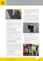
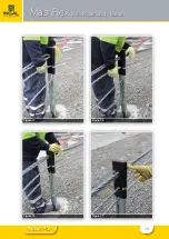
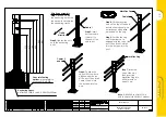
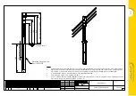
9. Ensure MashFlex cap is fully pushed down on post
and insert MashFlex Plug into hole on side of cap, the
plug is an interference fit and may require some light
force from a rubber mallet. Before inserting plug,
ensure the cable order is consistent and there are no
twists in the pattern, i.e. the third cable is consistently
in the third position for the entirety of the run. to the
two terminal posts (figures 15 and 16).
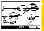
10. Insert the locking bolt into the cable anchor bracket,
refer figure 18.
6.9 Installation of Tension Bays
Tension bays are located at 300m centres and not more
than 150m from either anchor point. This section is to be
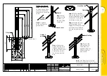
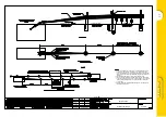
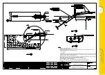
read in conjunction with drawing WR-MF-059.
For fences less than 600m:
1. Swage the stainless steel end fittings onto all
the cables and attach to the anchor bracket. The
procedure for swaging is contained in the FlexFence
Swaging Unit Safe Operating Procedure Manual.
The bottom rope is located nearest to the approaching
traffic face. Each end fitting is secured at the anchor
with one washer and two nuts. If using the standard
terminal, ensure safety check ropes are attached
before swaging.
Note: An inspection hole is drilled into each stainless steel
end fitting to ensure the wire rope cables are properly
inserted into the end fittings before swaging.
2. Pull the slack out of the wire ropes toward the other
anchor. This can be achieved by hand or by using a
sling equipped with a lever claw clamp.
3. At locations where the wire rope reels have been
temporarily joined, swage the end fittings onto
the cables and install a tension fitting. End fittings
should be positioned so that the end of the fitting is
a minimum distance of 100mm from the post.
4. After the slack has been removed from the fence,
attach the check ropes (if required), machine swage
the end fittings and attach to the trailing or low-end
anchor.
5. Identify the tension bay location(s).
6. Mark and cut out an 800mm section from bottom,
second from bottom and top cables. Move past the
adjacent post and cut the 800mm section from the
third from bottom cable. This offsetting of the tension
bay for this cable will help expedite the tensioning
process. It may be necessary to attach temporary
clamps one post back from the tension bay location
prior to cutting in order to prevent the cables from
retracting. End fittings should be positioned so
that the end of the fitting is a minimum distance of
100mm from the post. Refer drawing WR-MF-059
and figure 19.
7. Swage the end fittings to each cable and attach
the tension fittings. The procedure for swaging
is contained in the FlexFence Swaging Unit Safe
Operating Procedure Manual.
8. Attach the tensioning rig to the bottom cable and
tension from the bottom up. The procedure for
Tensioning is contained in the FlexFence Tension
Unit Safe Operating Procedure Manual. Each rope is
tensioned in accordance with Table 5.
For fences greater than 600m:
1. Attach the safety check ropes (if required) and
machine swage the cables at the leading or high-
end anchor tand attach to the anchor bracket.
2. Pull the slack out of the wire ropes towards the 1st
tension bay location. This can be achieved by hand or
by using a sling equipped with a lever claw clamp.
3. At the 1st tension bay location clamp the wire
rope cable to a post. Repeat process for each cable,
clamping each cable to a different post.
4. Cut the cables on the un-tensioned side of clamps
and machine swage fittings. Assemble the tension
fittings.
5. Relocate to the 2nd tension bay and repeat the
above process. Continue until all the tension bays are
completed.
6. Once the slack has been removed from the fence,
attach the check ropes (if required), swage the end
fittings and attach to the trailing or low-end anchor.
7. Once the cables are attached at the anchor bracket,
relocate to the centre tension bay.
8. Attach the tensioning rig and tension in accordance
with Table 5 from the bottom up.
9. Relocate from the centre bay outwards repeating the
tension process.
10. Once complete, relocate to the centre bay and repeat
tensioning in this bay only.
Note:
Upon completion, the tension bays shall not be
more than 90% (40mm gap) of their full extent so as to
allow for further adjustment. There should also be a min
40mm exposed thread beyond each nut.
It is recommended that concrete used for the construction
of anchor blocks and post footings be cured for a period
of 7 days prior to tensioning.
Содержание INGAL MashFlex MASH TL3
Страница 11: ...11 Release 07 22 MashFlex Wire Rope Safety Barrier Figure 10 Figure 11 Figure 12 Figure 13...
Страница 12: ...12 Release 07 22 MashFlex Wire Rope Safety Barrier Figure 14 Figure 15 Figure 16 Figure 17...
Страница 19: ...19 Release 07 22...
Страница 26: ...26 Release 07 22 Notes...
Страница 27: ...27 Release 07 22 Notes...


