background image

31

Diagnostics

Error Logs

For each error code there is an error log. Each entry 
in the log records the following information about the 
error:
•  the time and date when it first occurred
•  the time and date when it last occurred
•  the total number of occurrences
See Figure 31-1.

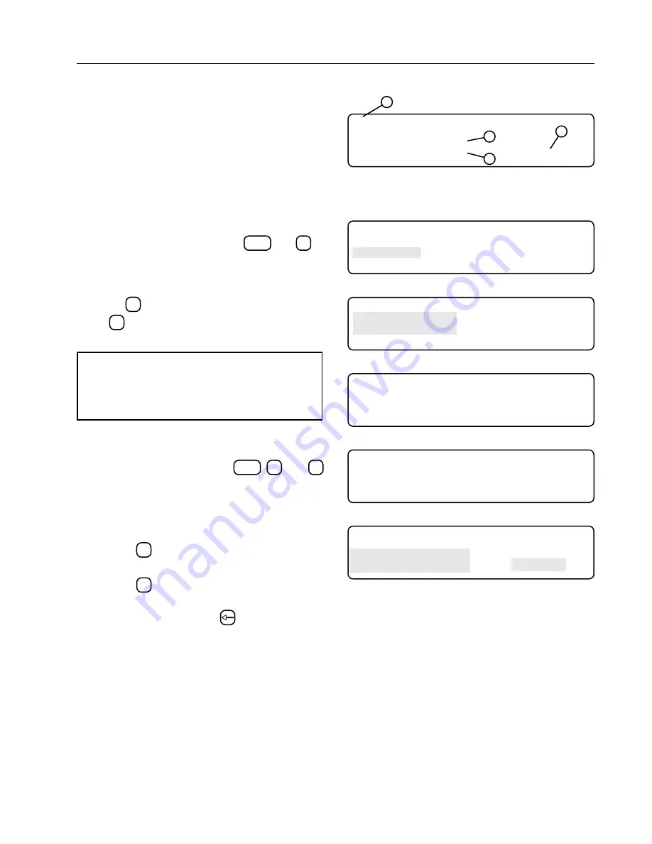
Viewing An Error Log

To view an Error Log, do the following:

1.  From the Status screen, press 

DIAGNOSTICS

 and 

2

 to 

display Error Log screen. See Figure 31-2. This 
will allows you to navigate through logged errors.

2.  To view a different System Review Log screen, 

press 

1

 to search backward toward screen 99 

or 

2

 to search forward toward screen 01. See 

Figure 31-3.

NOTE

• Viewing the Error Log screen clears the error 

codes from the Main Display screen until a 
new error is recorded.

Resetting An Error Log To Zero

To reset an Error Log to zero, do the following:

1.  Press the Diagnostics button 

DIAGNOSTICS

2

, and 

1


to display the E01 Error Log screen. See Figure 
31-4.

2.  Locate the desired error log screen to reset. See 

Figure 31-5.

•  Press 

1

 to search backward through the Er-

ror Logs.

•  Press 

2

 to search forward through the Error 

Logs.

3.  Press the Back Arrow key 

 two times.

The count is reset to zero and the first and last 
occurrences are set to the current time and date. See 
Figure 31-6.

4

E01   BATTERY   BACKED   RAM   -   CHECKSUM

FAILED   AT   POWER   UP
FIRST  :14:26:35 

12/28/99

LAST   :13:36:07 

01/04/00 

COUNT=  5

1

2

3

Figure 31-1 1. Error Code

2. First Occurrence Time and Date
3. Last Occurrence Time and Date
4. Total Occurrences

0 EXIT

3  SYSTEM REVIEW LOG

1  SYSTEM FAULTS

4  IO

2  ERROR LOG
PRESS ENTER  >

Figure 31-2

0  EXIT 
1  SEARCH BACKWARD
2  SEARCH FORWARD
PRESS ENTER  >

Figure 31-3

E01   BATTERY   BACKED   RAM   -   CHECKSUM

FAILED   AT   POWER   UP
FIRST  :00:00:00 

01/01/90

LAST   :00:00:00 

01/01/90 

COUNT=  0

Figure 31-4

E04   KEYPAD - POSSIBLE KEY STUCK,

CHECK KEYPAD CONNECTION
FIRST  :07:23:23 

07/08/07

LAST   :08:37:18 

07/09/07 

COUNT=  4

Figure 31-5 Selected Error Log

E04   KEYPAD - POSSIBLE KEY STUCK,

CHECK KEYPAD CONNECTION
FIRST  :12:26:35 

07/10/07

LAST   :12:26:35 

07/10/07 

COUNT=  0

Figure 31-6

Содержание Vflex

Страница 1: ...VFlex Corner Sequencing Control Panel Owner s Manual 0999114_B 2018 Valmont Industries Inc Valley NE 68064 USA All rights reserved www valleyirrigation com...

Страница 2: ...2...

Страница 3: ...alified Person 9 Overhead Power Lines 10 Minimal Lockout Tagout Procedure 11 Sequence Of Lockout 11 Restoring Equipment To Service 11 Safety 12 Operate Safely 12 Safety Decals 14 Overview 17 VCS Contr...

Страница 4: ...Key 24 Irr Chem 24 Seq Overrides 24 Crnr Angle 24 Position 24 Corner Angles 25 Machine Angles 26 Retracted Psi 27 Diagnostics 29 Diagnostics Screen 29 System Faults 29 Viewing System Faults 29 Status...

Страница 5: ...A1 Irrigation Machines Statement regarding Pressure Equipment Directive 97 23 EC The Crop Irrigation System is excluded from the scope of the Pressure Equipment Directive by the language of Article 1...

Страница 6: ...m the irrigation machine structure to the ground terminal on generator in order for the differential ground fault circuit breaker to work The resistance between the irrigation machine and the generato...

Страница 7: ...amage the equipment Safety Messages Safety messages in this manual are preceded by the hazard symbol and one of three words danger warning or caution These messages alert you to potential hazards that...

Страница 8: ...angles and ladders in areas with energized power lines exposed conductors or circuit parts work practices such as the use of insulation guarding and material handling techniques must be used to minimi...

Страница 9: ...GROUNDED PARTS ON THE OTHER SIDE EXPOSED LIVE PARTS ON ONE SIDE OF WORK SPACE AND EXPOSED LIVE PARTS ON THE OTHER SIDE 30 in 760 mm MINIMUM OR WIDTH OF ENCLOSURE WHICH EVER IS GREATER 78 in 1980 mm M...

Страница 10: ...tal conditions will increase the possibility of electrocution and require additional consideration Transmitter towers can induce the equipment or materials being handled with an electrical charge Befo...

Страница 11: ...4 Deactivate the energy isolating device s so that the machine or equipment is isolated from the energy source s 5 Lock out the energy isolating device s with assigned individual lock s 6 Stored or re...

Страница 12: ...ld be presented annually and the service manager should ensure employees fully understand the safety messages and what to do in case of emergencies EMERGENCY STOPPING The machine can be stopped at any...

Страница 13: ...bly the tallest object in the field which makes it a good lightning receptor CAUTION DO NOT OVERSIZE FUSES Fuses are sized for the protection of a specific machine Be certain you have the proper fuse...

Страница 14: ...decals For replacement of any decal contact your local Valley dealer KEEP TRAY CLEAR OF TOOLS PARTS OR DEBRIS PIPE MOVES WITHOUT WARNING DO NOT TOUCH MOVING CRADLE OR PIPE CLOTHING FINGERS OR LIMBS MA...

Страница 15: ...s Read operating instructions Do not place fingers or objects near openings Do not use eye bolts or lifting hooks to lift anything except the product Disconnect power before maintenance Open all circu...

Страница 16: ...16 Safety Safety Decals Continued...

Страница 17: ...nitions Below are terms that are used throughout the instruction VCS VFlex Corner Sequencing Control Panel Corner The swing arm portion of an irrigation machine EEPROM Electronically Erasable Programm...

Страница 18: ...ntrol rod is used with the Angle Sensor Box See Figure 18 2 Run Cycle Box Mounted on the left side of the cradle See Figure 18 2 Inverted Leading Corner Orientation for all figures is based on standin...

Страница 19: ...control panel the control panel display shows the current machine status on the status screen See Figure 19 1 A short explanation of the status screen elements is given below and on the following pag...

Страница 20: ...n Status Menu Continued Function Keys The function keys are located on the far left side of the keypad See Figure 20 1 The function keys are used to program the panel view data and select options not...

Страница 21: ...rical value entry or programming sequence See Figure 21 1 NUMERIC ENTRY KEYS 2 4 1 6 3 5 Figure 21 1 1 Number Keys 2 Decimal Point Key 3 Minus Sign Key 4 Escape Key 5 Navigation Arrow Keys 6 Enter Key...

Страница 22: ...tus screen is displayed Screen Delays Any screen that is left for more than five minutes without pressing a key will revert back to the previously displayed screen The Status screen will eventually be...

Страница 23: ...communication with the Smart Tower Board STB is established Acquiring Satellites Screen Figure 23 3 shows the screen that appears while the system waits for the GPS Receiver to acquire signals from t...

Страница 24: ...screens Corner Angle Position Corner Angles and Machine Angles See Figure 24 4 Crnr Angle 5 Press PROGRAMS 2 and 1 to select the CRNR ANGLE option See Figure 24 5 Press 1 to Enable Press 0 to Disable...

Страница 25: ...ol umn to enter end angle See Figure 25 4 Enter end angle input 60 to 180 13 Press ENTER with cursor located in the STATE column to enter corner state See Figure 25 5 Press 1 to select Extension EXT P...

Страница 26: ...be the selected entry is the cursor position it will blink allowing the user to see the data being covered The and arrow keys will move the cur sor to the next or previous field The and arrow keys wil...

Страница 27: ...Psi This menu is only functional when pressure regulators are not selected See Figure 27 5 26 Press PROGRAMS and 3 to display the retracted psi screen See Figure 27 6 Press 1 to use current psi setti...

Страница 28: ...28 Operation...

Страница 29: ...successfully See Figure 29 3 This screen will be skipped if there is an active fault Instead the submenu with the highest priority active faults will be displayed like in the examples See Figure 29 4...

Страница 30: ...in the STB is corrupt E12 STB EEPROM CHECKSUM FAILED AT POWER UP EEPROM memory in the STB is corrupt E13 STB UNIT RESETS THIS IS LOGGED WHEN THE SOFTWARE RESETS STB reset unexpectedly there are a numb...

Страница 31: ...og screen See Figure 31 4 2 Locate the desired error log screen to reset See Figure 31 5 Press 1 to search backward through the Er ror Logs Press 2 to search forward through the Error Logs 3 Press the...

Страница 32: ...ch backward toward screen 99 or 2 to search forward toward screen 01 Press esc to exit to diagnostics screen See Figure 32 2 Example review screen Review xx is the review screen being viewed xx 01 to...

Страница 33: ...annel Channel 0 monitors voltage from the pressure transducer An acceptable range is between 1000 and 15 mV Channel 1 monitors voltage from the angle sen sor For more information see the Angle Setup s...

Страница 34: ...ays or press 0 or ESC to exit this screen GPS The Navigation screens inform you of the machine s current position and how far it has deviated from its intended path This read only information is in de...

Страница 35: ...TH TROUBLESHOOTING OR REPAIRING ELECTRICAL PROBLEMS SHOULD ONLY BE PERFORMED BY A QUALIFIED VALLEY DEALER ALWAYS CONTACTYOUR LOCAL VALLEY DEALER TO TROUBLESHOOT OR CORRECT ANY ELEC TRICAL PROBLEMS ON...

Страница 36: ...alley Dealer Figure 36 2 System Faults Figure 36 1 is a table that lists and describes possible system faults possible cause s whether the machine shuts down when the error occurs and corrective actio...

Страница 37: ...d in only one part of the system Contact your Valley Dealer E16 STB SENSOR REFERENCE ERROR 10 seconds NO Power Supply to the system sensors is not within the acceptable range Short in sensor cabling S...

Страница 38: ...e key ESC until the Re set screen appears See Figure 38 2 3 Press one of the following keys 1 Reset 2 Skip the reset function If no selection is made within 60 seconds the reset function skips PROBLEM...

Отзывы: