- 16 -
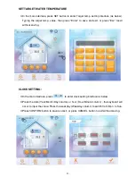
Figure 4
Figure 5
Figure 6
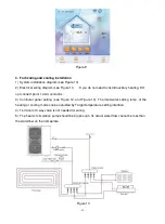
2. For only hot water installation
1) System installation diagram (see Figure 7).
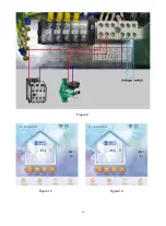
2) Electrical wiring diagram (see Figure 8). (If you do not need to install auxiliary heating, DO
not connect point 1,4 AC contactor)
3) Controller panel setting (see Figure 9).
4) Terminal of 3-way valve is not needed for wiring.
5) The head of circulation pump should be big enough. Its actual water flow cannot be less than
water flow on nameplate.
Содержание V1 Series
Страница 9: ...8 V1 18 V1 23 V1 28 V1 35...
Страница 10: ...9 Exploded view V1 08...
Страница 11: ...10 V1 13...
Страница 12: ...11 V1 18 23...
Страница 13: ...12 V1 28 35...
Страница 16: ...15 Figure 2 Figure 3...
Страница 18: ...17 Figure 7 Figure 8...
Страница 20: ...19 Figure 11 Figure 12 Figure 13...
Страница 23: ...22 Electrical Wiring Diagram 1 Single phase system V1 08...
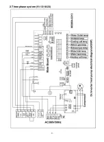
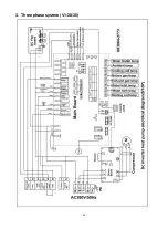
Страница 24: ...23 2 Three phase system V1 13 18 23...
Страница 25: ...24 3 Three phase system V1 28 35...
Страница 38: ...37 use G If the unit is soaking please contact the supplier factory or company of installment before use...


