- 14 -
7. The plumbing pipes must be installed with proper support to prevent possible damage due to
vibration.
Running water pressure should be kept over 196kpa. Otherwise, booster pump should be installed.
8. The acceptable operating voltage range should be within ±10% of the rated voltage.
⚫
The heat pump unit must be grounded /earthed for safety purposes.
Drainage and Condensation
Condensation will occur from the evaporator when the unit is running and drain at a steady rate,
depending upon ambient air temp. and humidity. The more humid the ambient conditions, the more
condensation will occur. The bottom of the unit acts as a tray to catch rainwater and condensation.
Keep the drain holes, located on the bottom pan of the unit base, clear from debris at all times.
Suggested Installation Methods
1. For h hot water installation
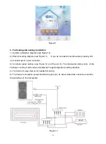
1) System installation diagram (see Figure 2).
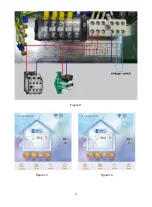
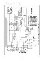
2) Electrical wiring diagram (see Figure 3).
(
If you don’t
install auxiliary heating, DO n o t
c o n n e c t point 1,4 AC contactor
)
3) Controller panel setting (see Figure 4, Figure 5, and Figure 6). Figure 4 shows that it is running
in hot water mode
,
Figure 5 /Figure 6 shows that it is running in heating or cooling mode.
4) 3-way valve: For domestic hot water mode, 3-way valve powers on. For underfloor heating or
cooling, 3-way valve powers off.
5) When both heating (or cooling) and domestic hot water don't reach the setting temp., hot water
is priority.
a) The hot water tank with coil for domestic hot water should be specially customized.
b) The heat exchange capacity of the coil should be
≥
the rated heating capacity of the heat pump.
c) The head of the circulation pump should be big enough. Its actual water flow cannot be less than
water flow on nameplate.
Содержание V1 Series
Страница 9: ...8 V1 18 V1 23 V1 28 V1 35...
Страница 10: ...9 Exploded view V1 08...
Страница 11: ...10 V1 13...
Страница 12: ...11 V1 18 23...
Страница 13: ...12 V1 28 35...
Страница 16: ...15 Figure 2 Figure 3...
Страница 18: ...17 Figure 7 Figure 8...
Страница 20: ...19 Figure 11 Figure 12 Figure 13...
Страница 23: ...22 Electrical Wiring Diagram 1 Single phase system V1 08...
Страница 24: ...23 2 Three phase system V1 13 18 23...
Страница 25: ...24 3 Three phase system V1 28 35...
Страница 38: ...37 use G If the unit is soaking please contact the supplier factory or company of installment before use...


