- 13 -
Installation Location
CAUTION!
1. DO NOT install the heat pump near to hazardous materials and places
2. DO NOT install the heat pump under deep sloping roofs without gutters which will allow rainwater,
mixed with debris, to be forced through the unit.
3. Place the heat pump on a flat slightly pitched surface, such as concrete or fabricated slab. This
will allow proper drainage of condensation and rainwater from the base of the unit. If possible, the
slab should be placed at the same level or slightly higher than the filter system/equipment.
Installation Details
All criteria given in the following sections reflect minimum clearances. However, each installation
must also be evaluated, considering the prevailing local conditions such as proximity and height of
walls, and proximity to public access areas. The heat pump must be placed to provide clearances
on all sides for maintenance and inspection.
1. The heat pump installation area must have good ventilation and the air inlet/outlet must not be
hindered.
2. The installation area must have good drainage and be built on a solid foundation.
3. Do not install the unit in areas accumulated with pollutions like aggressive gas (chlorine or
acidic), dust, sand and leaves etc.
4. For easier and better maintenance and troubleshooting, no obstacles around the unit should be
closer than 1m. And no obstructions within 2m, vertically, from the unit for air ventilation. (See
Figure 1)
Figure 1
5. The heat pump must be installed with shockproof pads to prevent vibration and/or imbalance.
6. Even though the controller is waterproof, care should be taken to avoid direct sunlight and high
temp. In addition, the heat pump should be placed to ensure quality viewing of the controller.
>
0.5m
>
0.5m
>
0.5m
>
2m
>
0.5m
>
0.5m
>
0.5m
Содержание V1 Series
Страница 9: ...8 V1 18 V1 23 V1 28 V1 35...
Страница 10: ...9 Exploded view V1 08...
Страница 11: ...10 V1 13...
Страница 12: ...11 V1 18 23...
Страница 13: ...12 V1 28 35...
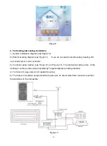
Страница 16: ...15 Figure 2 Figure 3...
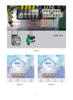
Страница 18: ...17 Figure 7 Figure 8...
Страница 20: ...19 Figure 11 Figure 12 Figure 13...
Страница 23: ...22 Electrical Wiring Diagram 1 Single phase system V1 08...
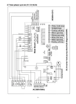
Страница 24: ...23 2 Three phase system V1 13 18 23...
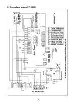
Страница 25: ...24 3 Three phase system V1 28 35...
Страница 38: ...37 use G If the unit is soaking please contact the supplier factory or company of installment before use...


