


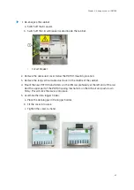


5. To connect the new isolator, use the existing wires in the isolator cable.
a. Discard the black wire end caps.
b. Observing polarity, connect the isolator wires to push-type terminals 1 and 2, and
the power wires to terminals 7 and 9 at the bottom of the isolator.
1
1
Galvanic isolator wires connected
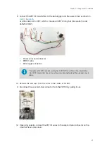
6. For wiring of the intrinsically safe screw terminals in the galvanic isolators, refer to the
wiring instructions printed on the side of the isolator and the
Safety Manual
leaflet
provided in the isolator packaging.
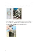
7. Reconnect power in CAB100A.
a. Reconnect the power wires in the fuse terminal blocks.
b. Switch on mains power.
More information
‣
CAB100A wiring diagrams (page 121)
‣
CAB100A layout diagrams (page 130)
Chapter 5 – Adding devices to CAB100A
41
Содержание CAB100
Страница 1: ...M212242EN B Installation Guide CMS Industrial Cabinet CAB100...
Страница 144: ......
Страница 146: ...www vaisala com...