background image

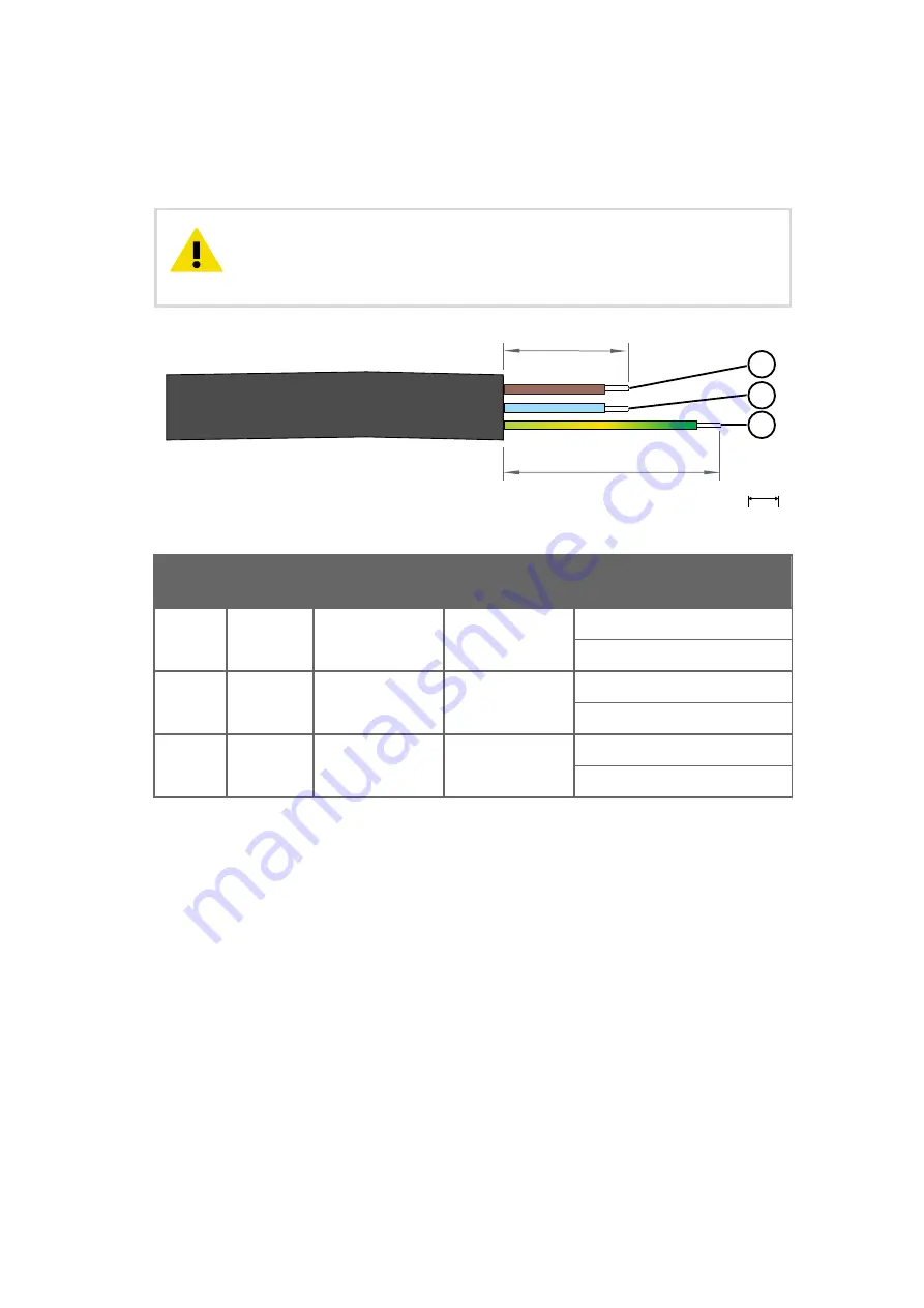
3. Strip approximately 100 mm (4 in) of the cable, and cut the phase and neutral wires to

the length of approximately 50 mm (2 in). If you are using a stranded wire, add cable
ferrules to the ends. 

Make sure that the grounding wire is longer than the phase and neutral

wires. Under mechanical stress, the grounding wire must be the last to disconnect
from the protective ground terminal.

CAUTION!

100 [3.94]

50 [1.97]

mm

[in]

1

2

3

Number

Wire

Wire color

(international)

Wire color (North

America)

Maximum wire cross-section

1

Phase L

Brown

Black

Solid wire: 4 mm

2

 (12 AWG)

Stranded wire: 2.5 mm

2

 (14 AWG)

2

Neutral N

Blue

White

Solid wire: 4 mm

2

 (12 AWG)

Stranded wire: 2.5 mm

2

 (14 AWG)

3

Grounding
PE/GND

Yellow/Green

Green

Solid wire: 4 mm

2

 (12 AWG)

Stranded wire: 2.5 mm

2

 (14 AWG)

CAB100 Installation Guide

M212242EN-B

30

Содержание CAB100

Страница 1: ...M212242EN B Installation Guide CMS Industrial Cabinet CAB100...

Страница 2: ...ange without prior notice Local rules and regulations may vary and they shall take precedence over the information contained in this document Vaisala makes no representations on this document s compli...

Страница 3: ...devices to CAB100A 33 5 1 Expanding PDT101 transmitter installation in CAB100A 33 5 2 Expanding safety barrier installation in CAB100A 36 5 3 Expanding galvanic isolator installation in CAB100A 39 6 A...

Страница 4: ...et PoE Data Logger Interface specifications 116 9 2 4 Third party component specifications 117 9 3 Spare parts and accessories 119 Appendix A Wiring diagrams 121 A 1 CAB100A wiring diagrams 121 A 2 CA...

Страница 5: ...h serial port server and 24 VDC power supply 125 Figure 17 Wiring diagram for CAB100B PDT101 model 126 Figure 18 Wiring diagram for CAB100B analog channel model with loop powered measurement devices 1...

Страница 6: ...tions 114 Table 14 DL4000 general specifications 114 Table 15 DL4000 memory specifications 115 Table 16 DL4000 recording span 115 Table 17 DL4000 current loop and voltage inputs 115 Table 18 vNet oper...

Страница 7: ...te M212294EN Vaisala CMS Industrial Cabinet CAB100 Wiring Diagrams Technical Reference M212284EN Vaisala CMS Industrial Cabinet CAB100 Quick Guide M211284EN Vaisala Differential Pressure Transmitter P...

Страница 8: ...d If you do not read and follow instructions carefully at this point there is a risk of injury or even death WARNING Caution warns you of a potential hazard If you do not read and follow instructions...

Страница 9: ...red trademark of Vaisala Oyj DIGI PortServer is a registered trademark of DIGI International Inc All other product or company names that may be mentioned in this publication are trade names trademarks...

Страница 10: ...al time monitoring of cleanrooms and industrial applications in multiple industries CAB100 is available in 2 models CAB100A small enclosure and CAB100B large enclosure The cabinets can be configured a...

Страница 11: ...thernet communication CAB100A Vaisala vNet Power over Ethernet Data Logger Interface with PoE option via RJ45 connector CAB100B Up to 2 serial to Ethernet devices via RJ45 DIGI PortServer TS4 Ethernet...

Страница 12: ...0A layout diagrams page 130 2 2 2 CAB100B models CAB100B is available in 4 pre configured models The communication interface in all CAB100B models is a multiport serial port server CAB100B model Maxim...

Страница 13: ...Mounting clamp for DL4000 data logger 2 DL4000 data logger 3 PDT101 transmitters 4 pcs 4 Cover plate 5 24 VDC fuses T2 5A 5 20 mm 2 pcs 6 110 240 VAC mains input and grounding point under cover plate...

Страница 14: ...nside CAB100A PDT101 model with vNet PoE 1 PDT101 transmitters 4 pcs 2 vNet PoE data logger interface 3 DL4000 data logger 4 Protective label Remove before installation 5 Grounding terminal block CAB1...

Страница 15: ...s 4 Holders for tubing 3 pcs 5 PDT101 transmitters 4 pcs 6 DL4000 data loggers 6 pcs 7 Serial port servers 2 pcs 8 Ethernet switch 9 24 VDC power block 10 24 VDC fuses T2 5A 5 20 mm 2 pcs 11 Cover pla...

Страница 16: ...Figure 5 CAB100A enclosure dimensions 600 23 62 500 19 69 206 8 11 618 24 33 mm in Figure 6 CAB100B enclosure dimensions The CAB100A enclosure is made of aluminium and has IP54 rating The CAB100B encl...

Страница 17: ...ing frame page 16 Installing CAB100B with mounting frame page 19 Enclosure flanges page 23 CAB100 specifications page 109 2 4 Regulatory compliances This product complies with the following electromag...

Страница 18: ...m outside the building where CAB100 is installed If CAB100 cannot be installed in an environment that meets the above criteria use a suitable surge protection device that has been installed following...

Страница 19: ...ion accessories 1 Hole for wall plug 4 pcs 2 Mounting slot 2 pcs 3 Wall plug 4 pcs 4 Hex wood screw M6 40 DIN571 A2 4 pcs 1 Drill holes into the wall Use the mounting frame as a guide 2 Place the wall...

Страница 20: ...to the wall with screws 4 Lift the enclosure into place Hang the enclosure onto the frame by sliding the mounting studs on the back of the enclosure into the mounting slots of the frame CAB100 Instal...

Страница 21: ...screw M6 16 ISO7380 A4 2 pcs 3 2 Installing CAB100B with mounting frame 4 mm Allen key 10 mm wrench Drill and 8 mm drill bits for making the installation holes Spirit level For safety reasons do not c...

Страница 22: ...e surge protection device that has been installed following local regulations CAUTION Do not drill holes in the backplate or the enclosure Drill shavings may damage the equipment inside the cabinet CA...

Страница 23: ...allation accessories 1 Hole for wall plug 4 pcs 2 Wall plug 4 pcs 3 Mounting slot 2 pcs 4 Hex wood screw M6 40 DIN571 A2 4 pcs 1 Drill holes into the wall Use the mounting frame as a guide 2 Place the...

Страница 24: ...to the wall with screws 4 Lift the enclosure into place Hang the enclosure onto the frame by sliding the mounting studs on the back of the enclosure into the mounting slots of the frame CAB100 Instal...

Страница 25: ...page 23 Table 4 Enclosure flanges and recommended use Number and type of flanges per cabinet model Type of connection Recommended flange to use CAB100A 1 flange on the top and 1 on the bottom of the e...

Страница 26: ...solators Bottom left hand flange only 3 3 1 Leading cables through rubber flange To preserve the IP rating of the enclosure make sure that you lead cables through the flanges as instructed CAUTION Pip...

Страница 27: ...2 Leading cables through stainless steel flange To preserve the IP rating of the enclosure make sure that you lead cables through the flanges as instructed CAUTION Cable cutters Cable stripping pliers...

Страница 28: ...the enclosure connect the cables and wires according to the wiring diagram To avoid strain on the connector make sure that you connect cables and wires properly Too much strain may cause the cable or...

Страница 29: ...hazard WARNING After disconnecting the power cable dangerous voltages can exist for some time To avoid injury disconnect the power and discharge circuits before touching them WARNING CAB100 analog inp...

Страница 30: ...2 people CAUTION More information Wiring diagrams page 121 Layout diagrams page 130 4 1 1 ESD protection Electrostatic discharge ESD can cause immediate or latent damage to electronic circuits Vaisal...

Страница 31: ...ss to the disconnection device after it has been installed The disconnection device must remain easy to operate The AC mains cable is not included in the delivery Use an AC mains cable with a minimum...

Страница 32: ...e grounding wire must be the last to disconnect from the protective ground terminal CAUTION 100 3 94 50 1 97 mm in 1 2 3 Number Wire Wire color international Wire color North America Maximum wire cros...

Страница 33: ...nd neutral N wires to the circuit breaker the phase in the left hand wire terminal and the neutral in the right hand wire terminal 3 Mount the AC mains cable to the strain relief fixture located under...

Страница 34: ...In CAB100A PDT101 model with vNet PoE power the cabinet by connecting your Ethernet PoE cable to the vNet device 2 Switch on mains power User documentation for Vaisala vNet Power over Ethernet Data L...

Страница 35: ...essories page 119 Follow the steps below to add new PDT101 transmitters to an existing set of transmitters in CAB100A Note the different steps for 24 VDC and PoE powered models Refer to CAB100A layout...

Страница 36: ...ires to the wire terminal connector in the PDT101 with a small flat head screwdriver Connect the black wire in the wire set to the COM terminal and the red wire to the Vin terminal of PDT101 When conn...

Страница 37: ...b Switch on mains power 9 Reconnect power in vNet PoE powered CAB100A model a Reconnect the Ethernet PoE cable to the vNet device b Switch on mains power More information PDT101 calibration page 107...

Страница 38: ...Follow the steps below to add new safety barriers to an existing set of devices in CAB100A A maximum of 4 barriers can be housed inside CAB100A Refer to CAB100A layout diagrams page 130 when planning...

Страница 39: ...tmost barrier CAUTION a Make sure the blue end of the device with the intrinsically safe screw terminals faces up towards the top of the cabinet b Rest the locking mechanism at the back of the barrier...

Страница 40: ...f the intrinsically safe screw terminals at the blue end of the barrier refer to the wiring instructions printed on the side of the barrier and the Operating Instructions leaflet provided in the barri...

Страница 41: ...e Follow the steps below to add new galvanic isolators to an existing set of devices in CAB100A A maximum of 4 isolators can be housed inside CAB100A Refer to CAB100A layout diagrams page 130 when pla...

Страница 42: ...nd the leftmost isolator CAUTION a Make sure that the intrinsically safe blue screw terminals face up towards the top of the cabinet b Rest the locking mechanism at the back of the isolator on the DIN...

Страница 43: ...isolator wires connected 6 For wiring of the intrinsically safe screw terminals in the galvanic isolators refer to the wiring instructions printed on the side of the isolator and the Safety Manual le...

Страница 44: ...safety barriers or galvanic isolators per row in the cabinet In cabinet models with 5 to 8 data loggers you need 2 serial port servers One serial port server controls the traffic of maximum 4 data lo...

Страница 45: ...ct cover in the middle of the cabinet 4 Mount the new PDT101 transmitters on the DIN rail preferably at the left end of the rail Rest the upper part of the PDT101 locking mechanism on the DIN rail and...

Страница 46: ...ched to the connector 7 Mount the data logger on the DIN rail preferably at the right hand end of the rail Rest the logger holder locking mechanism on the DIN rail and push down firmly This will click...

Страница 47: ...The cable set for PDT contains wiring for 4 PDT101 transmitters If you install only 1 to 3 PDT transmitters leave the extra wires unconnected and the wire end caps in place 10 Remove the end caps from...

Страница 48: ...13 Follow the terminal block label markings on the PDT101 and plug the connector back in 14 Connect the data logger connector to the DL4000 data logger CAB100 Installation Guide M212242EN B 46...

Страница 49: ...PDT101 wire terminal connector 2 Data logger wires connected to data logger 3 Power wires connected to power block 17 Route the wires along the cable ducts 18 Insert any extra length of wire into the...

Страница 50: ...odel current model before ordering new devices as you cannot mix different types of PDT101 models in a cabinet installation For more information see Spare parts and accessories page 119 You can instal...

Страница 51: ...for example 3 PDT101 transmitters installed on a DIN rail and want to complete the set by installing a fourth one use the existing PDT101 wires present in the cable duct 1 De energize the cabinet a S...

Страница 52: ...d cable set for PDT 5 Assemble the data logger holder a Place the data logger in the logger holder b Fit the cover into place c Tighten the screw by hand 6 Connect the logger data cable to the RS 232...

Страница 53: ...to step 16 Use the cable set for PDT which is included in PDT Wiring Set Vaisala item code ASM213079SP When mounting the second third or fourth PDT101 transmitter on the DIN rail use the existing wire...

Страница 54: ...y pulling it out 12 Observing polarity connect the PDT101 wires to the wire terminal connector with a small flat head screwdriver 13 Follow the terminal block label markings on the PDT101 and plug the...

Страница 55: ...er wires disconnected in step 2 17 Route the wires along the cable ducts 18 Insert any extra length of wire into the cable ducts and replace the cable duct covers 19 Reconnect power in the cabinet a S...

Страница 56: ...net In cabinet models with 5 to 8 data loggers you need 2 serial port servers One serial port server controls the traffic of maximum 4 data loggers Make sure to number the data loggers as well as the...

Страница 57: ...right hand side of the cabinet 2 Remove the cable duct cover below the empty DIN rail reserved for the analog terminal block Remove also the long vertical cable duct cover in the middle of the cabine...

Страница 58: ...o the RS 232 serial port in the data logger Use a small flat head screwdriver to tighten the screw attached to the connector 7 Mount the data logger on the DIN rail preferably at the right hand end of...

Страница 59: ...ata logger and to the 24 VDC power block as shown in step 10 to step 12 below Use the cables in the Analog Wiring Set Vaisala item code ASM213078SP 1 2 1 Cable set for connecting data logger to analog...

Страница 60: ...o the analog channel terminal block 1 2 1 Logger to analog cable set 2 Power cable set 11 Connect the black terminal connector of the logger to analog cable set to the DL4000 data logger CAB100 Instal...

Страница 61: ...g channel terminal blocks are now mounted and connected 1 3 2 4 1 Logger to analog cable set connected to analog channel terminal block 2 Power cable set connected to analog channel terminal block 3 P...

Страница 62: ...CAB100B wiring diagrams page 126 CAB100B layout diagrams page 135 6 3 1 Analog input channel wiring of loop powered measurement devices Small screwdriver Cable cutters Cable stripping pliers CAB100 a...

Страница 63: ...e CAB100 analog terminal block The example device is Vaisala Humidity and Temperature Transmitter Series HMT120 transmitter See the HMT120 user documentation for more information on wiring inside the...

Страница 64: ...Numbering of the terminal block connectors runs 1 4 left to right 5 Connect the wires to the corresponding wire terminals inside the external measurement device wiring inside HMT120 shown here More i...

Страница 65: ...s own You can install only one type of device or measurement point PDT101 transmitters analog input channels safety barriers or galvanic isolators per row in the cabinet In cabinet models with 5 to 8...

Страница 66: ...reaker located inside the cabinet 1 Circuit breaker 2 Remove the cable duct from the bottom left corner of the cabinet where the safety barriers will be installed Set the cable duct and the screws asi...

Страница 67: ...e pre drilled screw holes in the backplate and the screws provided in the Safety Barrier Wiring Set Vaisala item code ASM213201SP 1 2 1 Partition plate 2 Mounting screw M4 8 ECO Fix Zn TX20 2 pcs Chap...

Страница 68: ...ver into place c Tighten the screw by hand 7 Connect the logger data cable to the RS 232 serial port in the data logger Use a small flat head screwdriver to tighten the screw attached to the connector...

Страница 69: ...vant when connecting wires in the intrinsically safe screw terminals of the barrier step 17 11 Mount the barrier on the DIN rail a Make sure the blue end of the device with the intrinsically safe scre...

Страница 70: ...connector 2 Safety barrier wires 3 Data logger connector The cable set for safety contains wiring for 4 safety barriers If you install only 1 to 3 devices leave the extra wires unconnected and the wir...

Страница 71: ...cable set to the DL4000 data logger 15 Connect the 24 VDC power wire connector to the power block located on the right hand side of the cabinet 1 2 1 Vertical cable duct 2 Power wires connected to pow...

Страница 72: ...nto place to the left of the partition plate Vaisala recommends that you label the cable duct cover with the text INTRINSICALLY SAFE CONNECTIONS Alternatively use a blue cable duct as shown in step 16...

Страница 73: ...ll only one type of device or measurement point PDT101 transmitters analog input channels safety barriers or galvanic isolators per row in the cabinet In cabinet models with 5 to 8 data loggers you ne...

Страница 74: ...er located inside the cabinet 1 Circuit breaker c Disconnect the safety barrier power wire connector from the power block located on the right hand side of the cabinet 2 Remove the cable duct cover ab...

Страница 75: ...to the RS 232 serial port in the data logger Use a small flat head screwdriver to tighten the screw attached to the connector 6 Mount the data logger on the DIN rail preferably at the right hand end o...

Страница 76: ...ant when connecting wires in the intrinsically safe screw terminals of the barrier step 15 9 Mount the barrier on the DIN rail a Make sure the blue end of the device with the intrinsically safe screw...

Страница 77: ...connector 2 Safety barrier wires 3 Data logger connector The cable set for safety contains wiring for 4 safety barriers If you install only 1 to 3 devices leave the extra wires unconnected and the wi...

Страница 78: ...inal connector of the cable set to the DL4000 data logger 13 Connect the 24 VDC power wire connector to the power block 1 2 1 Vertical cable duct 2 Power wire connected to power block CAB100 Installat...

Страница 79: ...o the wiring instructions printed on the side of the barrier and the Operating Instructions leaflet provided in the barrier packaging 16 Insert any extra length of wire into the cable ducts and replac...

Страница 80: ...own You can install only one type of device or measurement point PDT101 transmitters analog input channels safety barriers or galvanic isolators per row in the cabinet In cabinet models with 5 to 8 da...

Страница 81: ...reaker located inside the cabinet 1 Circuit breaker 2 Remove the cable duct from the bottom left corner of the cabinet where the galvanic isolators will be installed Set the cable duct and the screws...

Страница 82: ...re drilled screw holes in the backplate and the screws provided in the Galvanic Isolator Wiring Set Vaisala item code ASM213143SP 1 2 1 Partition plate 2 Mounting screw M4 8 ECO Fix Zn TX20 2 pcs CAB1...

Страница 83: ...cover into place c Tighten the screw by hand 7 Connect the logger data cable to the RS 232 serial port in the data logger Use a small flat head screwdriver to tighten the screw attached to the connec...

Страница 84: ...elevant when connecting wires in the intrinsically safe screw terminals of the isolator step 17 11 Mount the isolator on the DIN rail a Make sure the blue end of the device with the intrinsically safe...

Страница 85: ...3 24 VDC power wires and connector The galvanic isolator cable contains wiring for 4 isolators If you install only 1 to 3 devices leave the extra wires unconnected and the wire end caps in place 13 O...

Страница 86: ...able set to the DL4000 data logger 15 Connect the 24 VDC power wire connector to the power block located on the right hand side of the cabinet 1 2 1 Vertical cable duct 2 Power wires connected to powe...

Страница 87: ...into place to the left of the partition plate Vaisala recommends that you label the cable duct cover with the text INTRINSICALLY SAFE CONNECTIONS Alternatively use a blue cable duct as shown in step 1...

Страница 88: ...only one type of device or measurement point PDT101 transmitters analog input channels safety barriers or galvanic isolators per row in the cabinet In cabinet models with 5 to 8 data loggers you need...

Страница 89: ...located inside the cabinet 1 Circuit breaker c Disconnect the galvanic isolator power wire connector from the power block located on the right hand side of the cabinet 2 Remove the cable duct cover ab...

Страница 90: ...o the RS 232 serial port in the data logger Use a small flat head screwdriver to tighten the screw attached to the connector 6 Mount the data logger on the DIN rail preferably at the right hand end of...

Страница 91: ...vant when connecting wires in the intrinsically safe screw terminals of the isolator step 15 9 Mount the isolator on the DIN rail a Make sure the blue end of the device with the intrinsically safe scr...

Страница 92: ...VDC power wires and connector The galvanic isolator cable contains wiring for 4 galvanic isolators If you install only 1 to 3 devices leave the extra wires unconnected and the wire end caps in place 1...

Страница 93: ...cable set to the DL4000 data logger 13 Connect the 24 VDC power wire connector to the power block located on the right hand side of the cabinet 1 2 1 Vertical cable duct 2 Power wires connected to pow...

Страница 94: ...refer to the wiring instructions printed on the side of the isolator and the Safety Manual leaflet provided in the isolator packaging 16 Insert any extra length of wire into the cable ducts and replac...

Страница 95: ...ide When adding more measurement devices in CAB100B you may need to add more data loggers in the installation A second serial port server is needed when the number of data loggers exceeds 4 For instal...

Страница 96: ...to the serial port server holder as shown below Use the original washer and screw 2 1 1 Locking mechanism reattached to serial port server holder 2 Screws and washers provided in the serial port serv...

Страница 97: ...minal for Ethernet switch power wires with wires connected 7 For installations including an Ethernet switch Connect the serial port servers to the Ethernet switch using 2 RJ45 cables 8 Route the power...

Страница 98: ...uct from the left side of the cabinet 1 Data logger data cables connected to serial port servers 2 Serial port servers and Ethernet switch connected with RJ45 cables 3 Power wires connected to power b...

Страница 99: ...re information Third party component specifications page 117 Spare parts and accessories page 119 CAB100B wiring diagrams page 126 CAB100B layout diagrams page 135 Chapter 6 Adding devices to CAB100B...

Страница 100: ...off mains power 2 De energize the PDT101 transmitters as shown in the following steps 3 De energizing 24 VDC powered CAB100A model Disconnect the PDT101 power wires from the fuse terminal blocks loca...

Страница 101: ...it breaker located inside the cabinet b Disconnect the PDT101 power wire connector from the power block located on the right hand side of the cabinet 6 Unplug the wire terminal connector from the PDT1...

Страница 102: ...he new PDT101 on the DIN rail Rest the upper part of the locking mechanism on the DIN rail and push down firmly This will click the device into place 10 Use the existing wire terminal connector and pl...

Страница 103: ...er wires in the power block located on the right hand side of the cabinet b Switch on the circuit breaker c Switch on mains power 14 The new PDT101 is now mounted and connected Insert any extra length...

Страница 104: ...ce calibrated or faulty DL4000 data loggers 1 Switch off mains power 2 De energize CAB100A or CAB100B as shown in the following steps 3 De energizing 24 VDC powered CAB100A model Disconnect the PDT101...

Страница 105: ...nnector from the power block located on the right hand side of the cabinet 6 To unmount an existing data logger first disconnect the data logger connector from the data logger 7 Unmount the logger hol...

Страница 106: ...r in the logger holder b Fit the cover into place c Tighten the screw by hand 10 Connect the logger data cable to the RS 232 serial port in the replacement data logger Use a small flat head screwdrive...

Страница 107: ...C powered CAB100A model a Reconnect the power wires in the fuse terminal blocks b Switch on mains power 14 Reconnect power in vNet PoE powered CAB100A model a Reconnect the Ethernet PoE cable to the v...

Страница 108: ...the cabinet b Switch on the circuit breaker c Switch on mains power For instructions on configuring measurement units and scaling in DL4000 data loggers see Vaisala viewLinc Enterprise Server Version...

Страница 109: ...cribed in PDT101 adjustment page 107 8 2 PDT101 adjustment High accuracy pressure standard and high quality electrical meter for adjustment 2 5 mm 3 32 in flat head or crosshead screwdriver POWER HI L...

Страница 110: ...ressure Transmitter PDT101 Quick Guide M211284EN available for download at www vaisala com pdt101 8 3 Cleaning You can clean the CAB100 enclosure by wiping with a clean cloth moistened with mild deter...

Страница 111: ...VAC 50 60 Hz 0 5 A maximum 120 VAC Power supply module within cabinet 24 VDC 2 5 A Fused 2 A Power over Ethernet 1 12 30 VDC IEEE 802 3af 10Base T Mains fuse nominal 4 A Maximum power consumption CAB...

Страница 112: ...kg 12 lb Mounting frame only 2 1 kg 4 6 lb CAB100B Fully populated cabinet and mounting frame in shipping package Approx 30 kg 66 lb depending on model Enclosure with backplate 18 7 kg 41 lb Mounting...

Страница 113: ...ty requirements for electrical equipment for measurement control and laboratory Use Part 1 General requirements 2 1 Excluding CAB100 analog input channels which are not surge protected 2 Safety listin...

Страница 114: ...es bidirectional 60 Pa 0 25 in H2O Accuracy incl non linearity hysteresis repeatability and zero span calibration settings 0 4 span Long term stability 0 5 span year Response time 10 90 250 ms Warm up...

Страница 115: ...w frequency area of 80 120 Mhz it is possible that the current output of PDT101 can deviate max 0 8 with accuracy specified 0 4 Table 12 PDT101 inputs and outputs Property Description Value Process co...

Страница 116: ...fications Property Description Value Operating range 40 85 C 40 185 F and 0 100 RH non condensing Interfaces RS 232 serial USB Wifi module Ethernet and Power over Ethernet vNet Weight 76 g 2 7 oz Size...

Страница 117: ...ing span Recording span depends upon sample interval selected and number of channels enabled Please see table above Table 16 DL4000 recording span Sample interval Number of channels 1 2 3 4 10 seconds...

Страница 118: ...t inputs and outputs Property Description Value Ethernet connectivity IEEE 802 3af Class 1 1 bandwidth 10Base T Connectivity cable Category 5 5e RJ 45 connector 1 83 m 6 ft Operating voltage 2 12 30 V...

Страница 119: ...r IP address Other vNets on the subnet will automatically self configure Addressing DHCP RARP ARP Ping Static IP for IP address assignment Net BIOS name Firmware Field upgradable firmware Compliance E...

Страница 120: ...Galvanic isolator product information Property Description Value Product description Transmitter supply unit Ex i field circuit type 9160 13 11 11k Manufacturer R STAHL www r stahl com Manufacturer pa...

Страница 121: ...model PDT101 P4C Measurement range 60 Pa Safety barrier 210664 Galvanic isolator 212483 Serial port server DIGIKNNN 4 port model Serial port server holder for DIN35 rail ASM213139SP vNet PoE data log...

Страница 122: ...tor Wiring Set Galvanic isolator cable Data logger data cable Partition plate Data logger holder ASM213143SP Needed when adding galvanic isolators to CAB100 Note that the data logger is not included i...

Страница 123: ...te Enclosure DIN 35 Rail PE In L In N In 100 240VAC 50 60Hz X1 Fuse 2 x 2A F2 F3 Port Server 1 2 Ethernet Out F1 G1 1 2 3 4 Circuit Breaker 2P L N Power Supply Input AC 100 240V Output DC 24V 2 5A CBL...

Страница 124: ...PDT101 1 4 vNet Eth 15V out Pwr in Vout Vin com Vout Vin com Vout Vin com Vout Vin Ethernet PoE Base Plate Enclosure DIN 35 Rail PE In X1 CBL210784 CBL210799 Figure 13 Wiring diagram for CAB100A PDT10...

Страница 125: ...e 2 x 2A F2 F3 Serial Port Server 1 2 Ethernet Out F1 G1 1 2 3 4 Circuit Breaker 2P L N Power Supply Input AC 100 240V Output DC 24V 2 5A CBL210784 CBL210786 CBL210795 CBL210807 CBL210805 CBL210790 CB...

Страница 126: ...e Plate Enclosure DIN 35 Rail PE In L In N In 100 240VAC 50 60Hz X1 Fuse 2 x 2A F2 F3 Ethernet Out F1 G1 1 2 3 4 Circuit Breaker 2P L N Power Supply Input AC 100 240V Output DC 24V 2 5A CBL210784 CBL2...

Страница 127: ...ail PE In L In N In 100 240VAC 50 60Hz X1 Fuse 2 x 2A F2 F3 Serial Port Server 1 2 Ethernet Out 2 1 C C C C 3 4 Data Logger DL4000 F1 G1 1 2 3 4 Circuit Breaker 2P L N Power Supply Input AC 100 240V O...

Страница 128: ...sure DIN 35 Rail PE In L In DIN 35 Rail DIN 35 Rail N In 100 240VAC 50 60Hz nc nc nc nc 1 C 2 C 3 C 4 C PDT101 2 1 PDT101 2 2 PDT101 2 3 PDT101 2 4 Data Logger 1 DL4000 X1 Serial Port Server Port 1 4...

Страница 129: ...Logger 3 Data Logger 4 24VDC Outputs 1 C 2 C 3 C 4 C Data Logger 1 DL4000 Serial Port Server 1 Port 1 1 C 2 C 3 C 4 C Data Logger 2 DL4000 Serial Port Server 1 Port 2 1 C 2 C 3 C 4 C Data Logger 3 DL4...

Страница 130: ...Safety Barrier 3 1 2 3 4 Safety Barrier 4 1 2 Signal In Signal In Signal In Signal In F2 F3 Data Logger 1 Data Logger 2 Data Logger 3 Data Logger 4 Serial Port Server Port 1 4 Ethernet Out 24VDC Outpu...

Страница 131: ...n DIN 35 Rail DIN 35 Rail N In 100 240VAC 50 60Hz X1 1011 Galvanic Isolator 1 1 2 Signal In mA 7 9 1011 Galvanic Isolator 2 1 2 Signal In mA 7 9 1011 Galvanic Isolator 3 1 2 Signal In mA 7 9 1011 Galv...

Страница 132: ...y 1 Mounting clamp for DL4000 data logger 2 DL4000 data logger 3 PDT101 transmitters 4 pcs 4 Cover plate 5 24 VDC fuses T2 5A 5 20 mm 2 pcs 6 110 240 VAC mains input and grounding point under cover pl...

Страница 133: ...nts inside CAB100A PDT101 model with vNet PoE 1 PDT101 transmitters 4 pcs 2 vNet PoE data logger interface 3 DL4000 data logger 4 Protective label Remove before installation 5 Grounding terminal block...

Страница 134: ...ata logger 2 DL4000 data logger 3 Terminal block for analog input channels 4 Cover plate 5 24 VDC fuses T2 5A 5 20 mm 2 pcs 6 110 240 VAC mains input and grounding point under cover plate 7 Circuit br...

Страница 135: ...mp for DL4000 data logger 2 DL4000 data logger 3 Safety barriers 4 pcs 4 Cover plate 5 24 VDC fuses T2 5A 5 20 mm 2 pcs 6 110 240 VAC mains input and grounding point under cover plate 7 Circuit breake...

Страница 136: ...DL4000 data logger 2 DL4000 data logger 3 Galvanic isolators 4 pcs 4 Cover plate 5 24 VDC fuses T2 5A 5 20 mm 2 pcs 6 110 240 VAC mains input and grounding point under cover plate 7 Circuit breaker a...

Страница 137: ...input channels 4 Holders for tubing 3 pcs 5 PDT101 transmitters 4 pcs 6 DL4000 data loggers 6 pcs 7 Serial port servers 2 pcs 8 Ethernet switch 9 24 VDC power block 10 24 VDC fuses T2 5A 5 20 mm 2 pc...

Страница 138: ...Holders for tubing 3 pcs 4 DL4000 data loggers 3 pcs 5 Serial port server 6 24 VDC power block 7 24 VDC fuses T2 5A 5 20 mm 2 pcs 8 Cover plate 9 Circuit breaker and power supply module 10 110 240 VA...

Страница 139: ...3 pcs 3 Holders for tubing 3 pcs 4 DL4000 data loggers 8 pcs 5 Serial port servers 2 pcs 6 Ethernet switch 7 24 VDC power block 8 24 VDC fuses T2 5A 5 20 mm 2 pcs 9 Cover plate 10 Circuit breaker and...

Страница 140: ...s 4 Holders for tubing 3 pcs 5 DL4000 data loggers 4 pcs 6 Serial port server 7 24 VDC power block 8 24 VDC fuses T2 5A 5 20 mm 2 pcs 9 Cover plate 10 Circuit breaker and power supply module 11 110 24...

Страница 141: ...Safety barriers 16 pcs 3 DL4000 data loggers 4 pcs 4 Holders for tubing 3 pcs 5 Serial port server 6 24 VDC power block 7 24 VDC fuses T2 5A 5 20 mm 2 pcs 8 Cover plate 9 Circuit breaker and power su...

Страница 142: ...rs for tubing 3 pcs 5 DL4000 data loggers 4 pcs 6 Serial port server 7 24 VDC power block 8 24 VDC fuses T2 5A 5 20 mm 2 pcs 9 Cover plate 10 Circuit breaker and power supply module 11 110 240 VAC mai...

Страница 143: ...open 3 Cut the pins that connect the battery to the circuit board from the ends of the battery 4 Twist the battery off the circuit board To prevent short circuits protect the battery contacts with tap...

Страница 144: ......

Страница 145: ...of the warranty for each product Technical support Contact Vaisala technical support at helpdesk vaisala com Provide at least the following supporting information as applicable Product name model and...

Страница 146: ...www vaisala com...

Отзывы: