0020257297_06 Installation and maintenance instructions
63
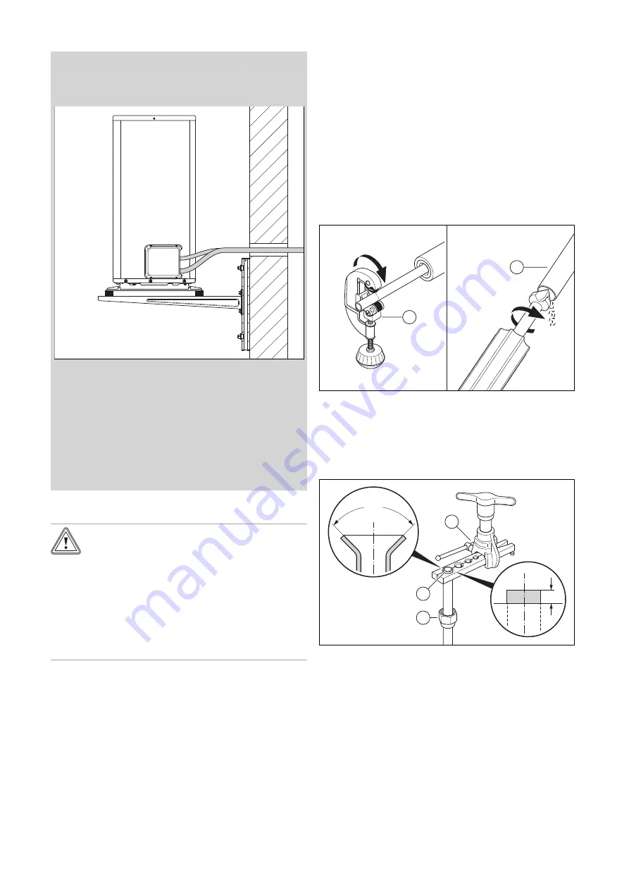
5.4
Routing refrigerant pipes to the product
Validity:
Wall-mounting
1.
Route the refrigerant pipe through the wall duct and
to the product.
2.
Bend the refrigerant pipes only once into their final
position. Use a bending spring or a bending tool to
avoid kinks.
3.
Ensure that the refrigerant pipes do not come into
contact with the wall and the product's casing sec-
tions.
4.
Route the refrigerant pipes in the wall duct with a
slight downward gradient to the outside.
5.
Route the refrigerant pipe centrally through the wall
duct without the lines touching the wall.
5.5
Routing refrigerant pipes in the building
Caution.
Risk of noise transmission.
If the refrigerant pipes are routed incorrectly,
noise may be transmitted to the building dur-
ing operation.
▶
Do not route the refrigerant pipes in
screed or masonry in the building.
▶
Do not route the refrigerant pipes through
living rooms in the building.
1.
Route the refrigerant pipes from the wall duct to the
indoor unit.
2.
Bend the refrigerant pipes only once into their final
position. Use a bending spring or a bending tool to
avoid kinks.
3.
Bend the refrigerant pipes at the right angle to the wall
and avoid mechanical tension during the routing.
4.
Ensure that the refrigerant pipes do not come into con-
tact with the wall.
5.
Use wall brackets with rubber insert to secure these.
Place the wall brackets around the thermal insulation of
the refrigerant pipe.
6.
Check whether oil elevation elbows are required
(
7.
If required, install oil elevation elbows in the hot gas
pipe.
5.6
Remove the cover for the hydraulic
connections
1.
Remove the screws at the upper edge.
2.
Release the cover by lifting it out of the stop.
5.7
Cutting the pipes to length and flaring the
pipe ends
1.
Keep the pipe ends downwards when working on them.
2.
Prevent the ingress of metal chips, dirt or moisture.
1
2
3.
Cut the copper pipe to length at a right angle using a
pipe cutter
(1)
.
4.
Deburr the inside and outside of the pipe end
(2)
. Re-
move all chips carefully.
5.
Unscrew the flare nut from the associated service
valve.
1
2
3
90°
1
6.
Slide the flare nut
(3)
onto the pipe end.
7.
Use a flaring tool to create flaring in accordance with
the SAE standard (90° flare).
8.
Insert the pipe end into the appropriate die matrix in the
flaring tool
(1)
. Allow the pipe end to protrude by 1 mm.
Clamp the pipe end.
9.
Widen the pipe end
(2)
using the flaring tool.
Содержание VWL 105/5 AS S2
Страница 203: ......


