ecoTEC plus 937 installation and maintenance manual
12
3.3
Scope of supply and accessories
1 1
10
9
8
7
6
5
4
3
2
1
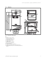
Fig. 3.1 Scope of supply and accessories
Pos. Quantity Name
1
1
Combi boiler ecoTEC plus
2
1
Bottom cover ecoTEC plus
3
1
Installation template
4
4
Isolating valves and filling loop
5
6
Connecting pipes (gas, heating, water, safety
valve)
6
5
Adapter set, consisting of connecting pipes
between the shift load storage tank and the
combi boiler for gas, heating flow and return and
water flow and return
7
2
Installation and connection accessories:
8
3
User, installation and service, flue installation
manuals
9
1
Bottom cover for shift load storage tank
10
1
Shift load storage tank
11
1
Hanging bracket
Table 3.1 Scope of supply and accessories
The shift load storage tank and the combi boiler are
delivered pre-assembled in one packaging unit.
Check that all parts have been delivered undamaged
(see Fig. 3.1 and Table 3.1 ).
h
Note!
At this stage do not yet remove the combi
boiler and the shift load storage tank from the
expanded polystyrene base to prevent any
damage.
3.4 Installation
location
h
Note!
When selecting the installation location observe
the regulations and recommendations for combi
boilers!
The installation location for the combi boiler and shift
load storage tank must permit proper connection of the
flue gas system to the combi boiler. In addition there
must be sufficient space for maintenance work and air
circulation around the combi boiler and the shift load
storage tank.
The Combi boiler and shift load storage tank can be
mounted together in any room you wish to choose.
In rooms with a bath or a shower, the special
requirements of BS 7671 (IEE Regulations), the electro-
technical stipulations of the Building Standards
(Scotland) Regulations and, in IE, the current issue of
IS 813 and the current ETCI Stipulations must especially
be observed.
3 General requirements


