Set-up 4
0020241403_02 ecoPOWER 3.0 /2, ecoPOWER 4.7 /2 Installation and maintenance instructions
9
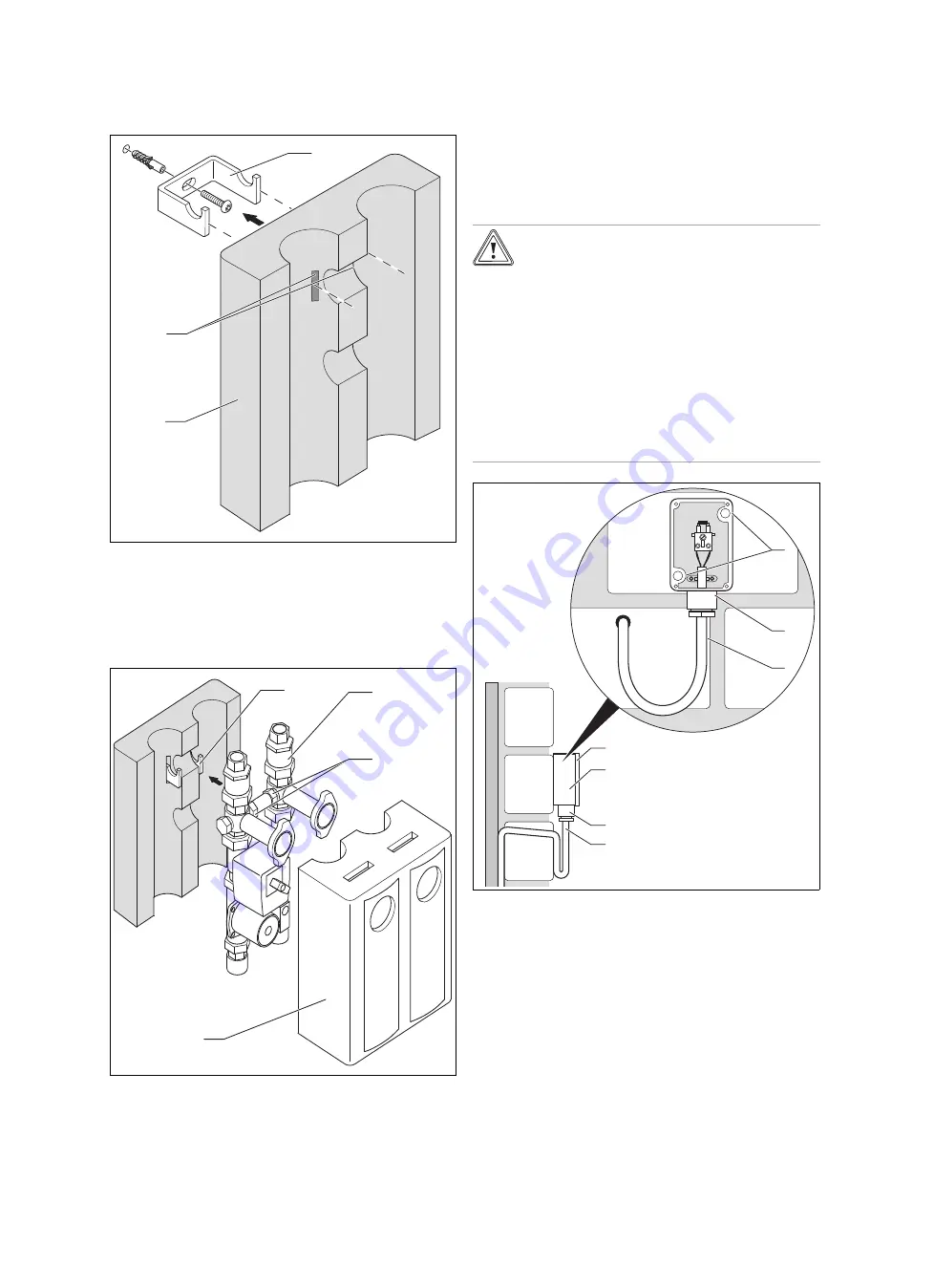
4.8.1
Installing the return retention group
1
3
2
1.
Drill a hole in the wall at a suitable location.
2.
Insert the plastic rawl plug.
3.
Screw in the wall bracket
(1)
tightly.
4.
Cut out the pre-punched slits
(2)
in the rear insulation
jacket
(3)
.
5.
Fit the insulation jacket on the wall bracket.
1
6
4
5
6.
Hook the return retention group
(4)
into the wall bracket
such that the wall bracket engages in the ball valve's
hex socket
(5)
on the right and left.
7.
Fit the front insulation jacket
(6)
onto the return reten-
tion group.
4.8.2
Installing sensors
You must connect different sensors depending on the config-
uration of the heating system and the control type. The basic
hydraulic diagram shows where to fit the sensors.
4.8.2.1 Installing the outdoor temperature sensor
Caution.
Risk of material damage caused by incor-
rect installation of the outdoor temperat-
ure sensor
Incorrect installation may cause damage to
the product or to the wall of the building, e.g.
from the penetration of dampness.
▶
Install the connection cable with a slight
incline to the outside and with a loop to
catch drips.
▶
Install the outdoor temperature sensor
with the grommet downwards.
5
4
2
3
1
2
3
1.
Mark a suitable position on the external wall. Observe
the cable laying for the outdoor temperature sensor.
2.
Route the connection cable
(3)
on-site with a slight in-
cline to the outside and with a loop to catch drips.
3.
Remove the housing cover
(5)
from the outdoor temper-
ature sensor.
4.
Position the housing cover on the external wall and
mark the drill holes through the mounting holes
(1)
.
5.
Drill two holes.


